EasyManua.ls Logo

Pentair 920 Series User Manual

Pentair 920 Series
82 pages
To Next Page IconTo Next Page
Page #1 background imageLoading...
Page #1 background image
1 / 82
EN- Raychem920series-IM-H5687405/15
INDUSTRIAL HEAT TRACING SOLUTIONS
920 Series Heat Trace Controller
InstallatIon, operatIng and MaIntenance InstructIons
A/B
ALARM
LOCK
MONITOR
CONFIG
STATUS
ALARM
OUTPUT
SHIFT
ENTER
BACK
Raychem
920 SERIES
PROGRAMMABLE DUAL POINT
HEAT TRACING CONTROLLER
Tx
Rx
A
B
A/B
ALARM
MONITOR
CONFIG
STATUS
ALARM
OUTPUT
SHIFT
BACK
ENTER
Raychem
920 SERIES
LOCK
Firmware versions # up to V3.2X

Table of Contents

Question and Answer IconNeed help?

Do you have a question about the Pentair 920 Series and is the answer not in the manual?

Pentair 920 Series Specifications

General IconGeneral
BrandPentair
Model920 Series
CategoryNetwork Router
LanguageEnglish

Summary

What's New in Raychem 920 Series

Important Warnings and Notes

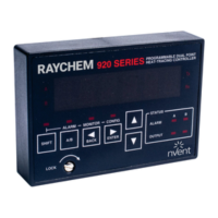
Highlights key icons and important information for safe operation.

Section 2: Installation and Wiring

Initial Inspection and Safety Considerations

Covers initial inspection procedures and operator safety during installation.

Wiring Connections for the 920 Series

Temperature Sensor Connections

Details on how to connect temperature sensors (RTDs) to the controller.

Power Connections

Guidelines for connecting power to the controller unit.

Initial Power-Up and Testing

Input Power Configuration

Describes how to configure the controller's input power source.

Initial Cable Test and Start-up Delay

Procedures for initial cable testing and understanding the random start delay.

920 Setup Procedures

Section 3: Programming and Configuration

Control Point Setup Parameters

Control Setpoint Temperature

Setting the desired temperature for the heat trace circuit control.

Switch Control Mode and Proportional Band

Selecting control modes and configuring the proportional band setting.

TS Fail Mode and Sensor Control Modes

Configuring TS fail mode and selecting temperature sensor control modes.

Advanced Configuration Settings

Load Shedding Enabling and Setpoint Limits

Enabling load shedding and setting console setpoint maximum/minimum.

Common Controller Setup

Temperature Alarms Configuration

TS Failure and Low Temperature Alarms

Setting up TS failure and low temperature alarms for sensors.

High Temperature Alarms and Filter Times

Configuring high temperature alarms and their associated filter times.

Other Alarms Configuration

Communications Setup

Operator Console Functions

Configuration Copy Utilities

Section 4: Monitored Parameters

Maintenance Data Tracking

Section 5: Control Modes

Load Shedding and TEMPBUST™ Control Modes

Load Shedding Control Mode

Description of the load shedding control mode operation.

TEMPBUST™ Master and Slave Configuration

Configuring TEMPBUST™ master and slave controller setups.

Section 6: Troubleshooting

Common Problem Areas and RTD Issues

Identifying common problems, RTD issues, and troubleshooting steps.

Ground Fault Troubleshooting

Diagnosing and resolving ground fault issues.

Common Alarms Analysis

Section 7: Maintenance

Operator Maintenance and Replaceable Parts

Guidelines for operator maintenance and information on replaceable parts.

Appendix A: Specifications

Appendix C: Wiring Diagrams

Appendix D: HTC Load Shedding Sequence