27 / 82
EN- Raychem920series-IM-H5687405/15
INDUSTRIAL HEAT TRACING SOLUTIONS
Setting: REMOTE or EXT. INPUT
Procedure: If the override signal will be generated remotely and received by the HTC via the
optional communications interface, select REMOTE as the OVERRIDE SOURCE. If the override
signal will be received by the HTC via the external input terminals on the 920 terminal board,
select EXTERNAL INPUT as the OVERRIDE SOURCE.
IMPORTANT:
• IftheEXTERNALINPUTisnotconfiguredaseitherINHIBITorFORCEONthenOVERRIDE
SOURCE will always automatically be set to REMOTE. See section 3.6.3 on page 29 for further
details.
• Iftheautocyclefeatureisenabled,itwillcontinuetofunctionevenwhenanINHIBIToverride
signal is being received as long as load shedding is not active.
• Fail-safemodeisinactiveifanINHIBIToverridesignalisbeingreceived.
• Loadsheddingandfail-safemodeareinactiveifaFORCEONoverridesignalisbeingreceived.
• OnlytheLOWTSALARMSfortemperaturesensorsusedbytheTSCONTROLMODEareinactive
if an INHIBIT override signal is being re-ceived.
3.5.28 LOAD SHEDDING ENABLING
Purpose: The load shedding function allows the controller output to be forced OFF by way of a
remote contact input on the 780 Group Com-munications Controller or using the communications
port and an upstream device. It may be used to turn OFF the output of one or more con-trollers
in order to reduce energy consumption to avoid peak demand surcharges, remove power from
unused circuits, or remove power from circuits that may be subjected to steam cleaning.
Setting: ENABLE or DISABLE
Procedure: Enable or disable the load shedding control mode as desired.
IMPORTANT:
• TocompletelyconfiguretheHTCforloadsheddingoperation,thefollowingadditional
parameters must be set up if using the Model 780/GCC-9000:
– Fail-safe mode
– Load shedding GCC contact association
• TheseadditionalparametersmayonlybeaccessedusingtheGroupCommunications
Controller. See the appropriate section of the GCC manual for further details.
• Fail-safemodeisnotsupportedwhenusingproportionalambientSSRmodeorproportional
ambient contactor mode.
• Fail-safemodeisnotsupportediftheTSCONTROLMODE=EXT.INPUT,FAILOFF/ON.
• Forfail-safemodetofunction,atleastoneLOWTSALARMofthecontrollingtemperature
sensor(s) must be enabled and the corresponding LOW TS ALARM temperature setting must be
less than the CONTROL SETPOINT temperature.
3.5.29 CONSOLE SETPOINT MAXIMUM (V3.11 AND UP)
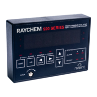
IMPORTANT: The CONSOLE SETPOINT MAXIMUM is not displayed on the optional 920 Operator
Console.
Purpose: When using an optional 920 Operator Console (for V3.11 and up) the maximum setting of
the CONTROL SETPOINT temperature may be limited to the CONSOLE SETPOINT MAXIMUM value.
This is a safety feature to prevent users in the field from modifying the CONTROL SET-POINT
temperature setting to a dangerous level.
Range: –76°F to 1058°F (–60°C to 570°C)
Procedure: Adjust the CONSOLE SETPOINT MAXIMUM temperature value to limit the maximum
allowable CONTROL SETPOINT TEMPERATURE that may be set using the optional 920 Operator
Console. The CONSOLE SETPOINT MAXIMUM may only be set using a communicating device such
as the Model 780/GCC-9000. See the 780/GCC-9000 manual for the proper procedure.
3.5.30 CONSOLE SETPOINT MINIMUM (V3.11 AND UP)
IMPORTANT: The CONSOLE SETPOINT MINIMUM is not displayed on the optional 920 Operator
Console.
Purpose: When using an optional 920 Operator Console (for V3.11 and up) the minimum setting of
the CONTROL SETPOINT temperature may be limited to the CONSOLE SETPOINT MINIMUM value.

 Loading...