6 / 82
EN- Raychem920series-IM-H5687405/15
INDUSTRIAL HEAT TRACING SOLUTIONS
SECTION I OVERVIEW
1.1 CONTROLLERS COVERED BY THIS MANUAL
This document covers the 920 Series of heat trace controllers and available options. The
information coincides with the specific releases of firmware for the 920 product which are listed
on the cover. As Pentair Thermal Managament releases new firmware to modify or enhance
the product significantly, new documentation will accompany these releases. To ensure that
you are using the correct documentation for your particular version of controller, please check
the firmware version number of the 920 against the version number listed on the front of this
manual. This can be displayed using the optional 920 Operator Console or a communicating
device. As subsequent changes are made, supplements to this document will be included in
manuals shipped after the firmware is released. Supplements will make specific reference to the
operational or functional changes.
1.2 PRODUCT OVERVIEW
1.2.1 DESCRIPTION
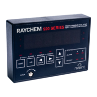
The 920 Series Heat-Tracing Controller controls, monitors, and communicates alarms and data
for one or two heating circuits. As a dual-point device, it offers a complete range of control and
monitoring features, as well as superior reliability compared to multipoint systems. Its modular,
scalable architecture yields cost-effective multipoint assemblies without the expense of additional
control points that are not required. Available for use with external solid-state relays (SSRs) or
contactors in either one-, two-, or three-pole configurations and the ability to switch loads up to
600 Vac makes the 920 the most versatile product on the market.
1.2.2 FEATURES
A detailed description of available features can be found in Section III of this manual. Highlights of
specific features are included in the following text.
Front Display
The control module includes LED status indicators to show output and alarm conditions. Using
the optional 920 Operator Console, the setpoint temperature, actual control temperature, and load
current are immediately accessible to plant operators and maintenance staff. The display units are
field selectable for °F or °C.
–40°F to 140°F (–40°C to 60°C) Operation
Extended temperature operation permits installation in all but the harshest environments. SSR
output modules are limited to operating ambient temperatures of 104°F (40°C) without derating.
Single or Dual Temperature Sensor Inputs
The ability to use one or two temperature sensor (TS) inputs for each control point allows the
selection of one of eleven control modes and programming of all temperature parameters.
High and Low Temperature Alarms
High and low temperature alarms are offered for both inputs of each control point.
High and Low Current Alarms
Low current alarm is more than just a continuity level alarm. The 920 offers full adjustment over
the entire current measurement range for both high and low current alarm limits.
Solid State or Contactor Output
The 920 is available with externally-mounted solid-state relay (SSR) output switches or contactors.
With the SSR option, the user may select a time-proportional control algorithm, a simple
deadband mode, or one of two ambient control algorithms. The contactor versions always use
either the deadband mode or the proportional ambient contactor mode. Switching device failure
alarms are supported for both types of output devices.

 Loading...