371885 (REV 12/2016) 5
English
Booster Pump Installaon
Please refer to the instrucons included with your booster pump for installaon informaon.
Please follow these instrucons carefully.
INSTALLATION
Calculang Cleaner Speed/RPM
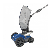
To determine whether the BLUEFURY
®
LITE Pressure Side Pool Cleaner is receiving the proper water pressure:
1. Turn o the pool pump, and carefully remove the cleaner from the pool.
2. Mark the front re/wheel with a marker, such as a blade of grass stuck under the re.
3. Have someone restart the pool pump and booster pump while you place the cleaner just beneath the pool’s water surface.
Note: Be sure to hold onto the sweep hose to avoid geng wet, as ow will return to the sweep hose when the pump is
restarted.
4. Count the number of full rotaons made by the marked wheel over a period of one minute. The number of rotaons will give
you the revoluons per minute; or RPM’s.
Note: Be sure that the back-up valve isn’t cycling at this me.
5. For proper performance, the BLUEFURY LITE cleaner operates between 35 - 42 RPMs.
If the RPM is below 35, call your local Pool Professional or contact Pentair’s Technical Support Department.
If the RPM is higher than 42, adjust the valve at the wall ng, as described under “Adjusng Water Flow to the Cleaner” on
page 8, unl the RPMs fall back under 42 RPM.
Installing the Wall Fing and Adapter
1. Remove and disconnect any exisng pool cleaner and/or
wall ng.
2. Switch on the ltraon pump and booster pump, to ush
out the plumbing line.
3. Switch o lter pump and booster pump.
4. If using a wall ng adapter produced by a
manufacturer other than Pentair, ensure that the red or
blue ow restrictor plate is removed from the from the
wall ng adapter before connuing to next step.
The restrictor plate can be easily removed by pressing it
out with your thumbs (See Figure 1).
Note: Failure to remove the ow restrictor plate from a
non-Pentair wall ng adapter will prevent the cleaner
from receiving enough water ow. This will lead to a slow
cleaner and longer cleaning cycles.
5. Insert wall ng adapter into the dedicated 1-1/2” NPT
threaded return line. Hand ghten unl snug. See Figure
2.
6. Align wall ng with the quick lock pegs inside the wall
adapter. Push the wall ng into the wall adapter unl
it booms out. Twist 1/4 turn clockwise to lock the wall
ng. Pull gently outward to engage quick lock pegs.
See Figure 2.
Figure 2
Installing the Wall Fing
LOW
HI
Wall Fing Adapter
(Shown Installed)
O-Ring
Wall Fing
Quick
Lock Peg
Figure 1
Flow Restrictor
Plate
Wall Fing Adapter
(Shown Uninstalled)
 Loading...