7
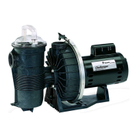
CHALLENGER
®
Centrifugal Pump Installation and User’s Guide
SERVICING
This section describes how to service the Challenger
®
Centrifugal Pump.
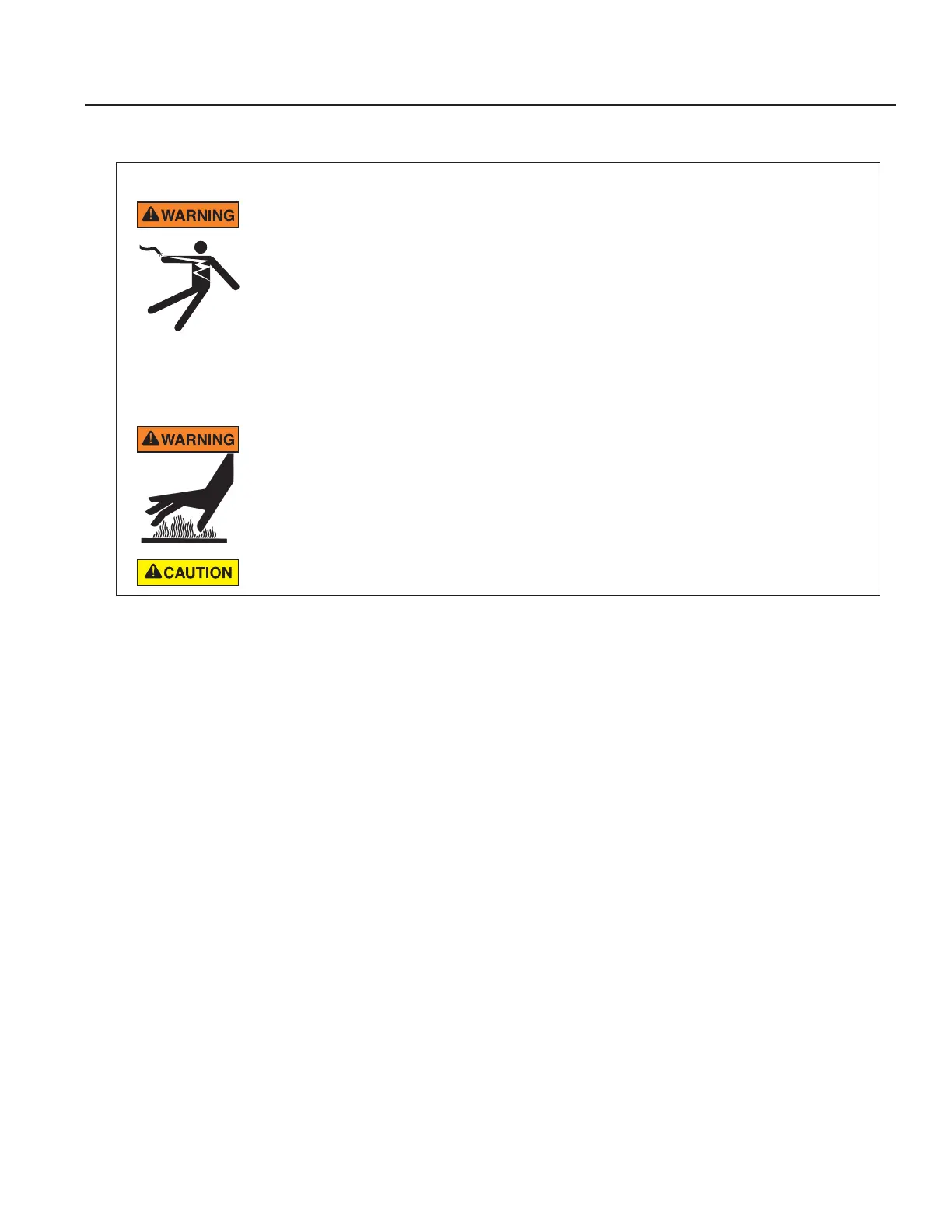
RISK OF ELECTRICAL AND ELECTROCUTION
This pool pump must be installed by a licensed or certified electrician or a qualified pool
serviceman in accordance with the National Electrical Code and all applicable local codes
and ordinances. Improper installation will create an electrical hazard which could result in
death or serious injury to pool users, installers, or others due to electrical shock, and may
also cause damage to property.
Always disconnect power to the pool pump at the circuit breaker before servicing
the pump. Failure to do so could result in death or serious injury to serviceman, pool
users or others due to electric shock.
Read all servicing instructions before working on the pump.
DO NOT open the strainer pot if pump fails to prime or if pump has been operating without
water in the strainer pot. Pumps operated in these circumstances may experience a build
up of vapor pressure and may contain scalding hot water. Opening the pump may cause
serious personal injury. In order to avoid the possibility of personal injury, make sure the
suction and discharge valves are open and strainer pot temperature is cool to touch, then
open with extreme caution.
Be sure not to scratch or mar the polished shaft seal faces; seal will leak if faces are damaged.
Pump Disassembly
All moving parts are located in the rear sub-assembly of this pump. Refer to Figure 4 on page 9 for an illustrated
parts view.
Tools required:
• Adjustable wrench.
• 1/4 inch flat-blade screwdriver.
• 9/16 inch open end wrench.
• Rubber Mallet
To remove and repair the motor sub-assembly perform the following procedures:
1. Turn off the pump circuit breaker at the main panel. Close suction and discharge valves to relieve system
pressure.
2. Drain the pump by removing the drain plugs. The drain plugs can be removed by hand. No tools are needed.
3. Loosen the band clamp by turning the band clamp knob counter-clockwise. The band clamp holds the rear-
subassembly to the housing (strainer pot/volute).
4. Remove the rear sub-assembly from the housing (strainer pot/volute) and place the band clamp to the side.
Note: If the band clamp does not separate from the pump housing and seal plate when loose, lightly tap the
top of the band clamp with a rubber mallet. This will free the clamp from the housing.
5. Place the rear sub-assembly upright and on a flat surface. Use a 1/4 inch flat blade screwdriver to remove
the three (3) holding screws located on the diffuser.
6. Remove the diffuser and diffuser spacer from the rear sub-assembly.
7. Use the 1/4 inch flat blade screwdriver to remove the impeller screw located in the center of the pump’s impeller.
Note: The impeller screw is a left-handed thread and loosens in a clockwise direction.
 Loading...