3
pulled, it may be necessary to shift cord leads back and forth
to guide the insulated terminals through the hole in the motor
housing. Once the terminals have cleared the hole, gently pull
cord until terminals are completely outside motor housing. Then
simply disconnect terminals to remove cord.
To install new cord, reconnect terminals (black to black, white to
white, green to green), and guide terminals back through hole
in motor housing. Once terminals have passed through the hole,
retighten the cord nut into housing. Tighten nut firmly but do not
overtighten.
The power cord should be replaced if it has been damaged in any
way or the cord jacket has become brittle with age.
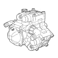
MOTOR TYPE
The D1C20-21 Series grinder pump contains a 3/4 frame, 2 HP,
single phase, 60 Hz, 3450 RPM, capacitor start - capacitor run
motor with Class F insulation and built-in on-winding overload
protection. Motor has upper and lower ball bearings and is oil-
cooled and lubricated. Resistance at motor leads is 9.7 ohms.
n CAUTION! THE D1C20-21 SERIES GRINDER PUMP SHOULD
NEVER BE WORKED ON WITHOUT FIRST DISCONNECTING THE
POWER CORD.
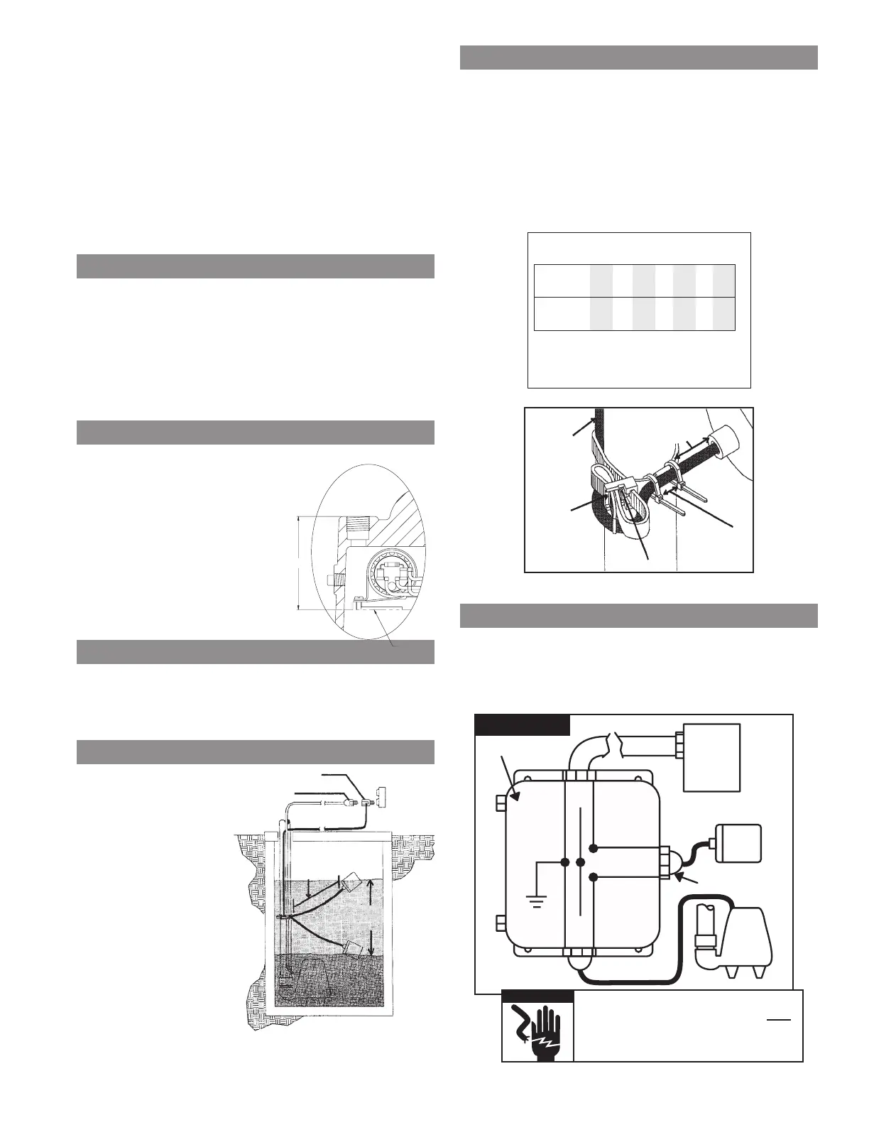
OIL TYPE
The motor housing contains dielectric
transformer oil to provide good heat
transfer and lubrication of ball bearings;
no other lubrication is required. Oil level
may be checked by removing the nut
(item 15C) and washers from the top
of the motor housing. The oil should be
filled to the bottom of the end shield
(see figure 1). Do not overfill with oil.
Only dielectric transformer oil obtained
from an authorized service center
should be used.
PUMP SWITCH INSTALLATION
INSTRUCTIONS
NOTE: In accordance to third party approval, pump must be
submerged a minimum of 8-1/2" from bottom of the legs on volute
case during operation.
MOUNTING THE SWITCH
1. Determine pumping
range for installation
(see Figures A and B).
Do not tether less than
3-1/2" (9 cm) from
pipe.
2. Tighten strap around
discharge pipe keeping
switch cable between
strap and pipe to
prevent slippage (see
Figure C).
3. Space small ties at
least 1" (2.5 cm) apart
(see Figure C). To read-
just ties, press small tie
tabs down.
4. To lock releasable tab, run remaining strap between tab and
head. Tuck strap back through head (see Figure C).
PIGGYBACK PLUG INSTALL
n Electrical outlet must not be located in pump chamber.
n Electrical outlet voltage, piggyback plug voltage, and pump
voltage must match.
1. Follow steps 1 through 4 of “Mounting the Switch.”
2. Insert switch’s piggyback plug into outlet.
3. Plug pump into piggyback plug (see Figure A).
4. Check installation. Allow system to cycle to ensure
proper operation.
DIRECT WIRE INSTALL
1. Follow steps 1 through 4 of “Mounting the Switch.”
2. Wire switch as shown below.
3. Check installation. Allow system to cycle to ensure
proper operation.
pump plug
switch plug
tether
length
pumping
range
Fig. A
Determining Pumping Range
In Inches (1 inch = 2.5 cm)
tether
3.5 6 10 14 18 22 24
length
pumping
7 10 16 22 28 33 36
range
Use only as a guide. Pumping ranges are based on
testing in nonturbulent conditions. Range may vary
due to water temperature and cord shape. Note: As
the tether length increases, so does the variance of the
pumping range.
Fig. B
Fig. C
secure
cable
under
strap
strap
head
space ties
1 inch
(2.5 cm) apart
releasable tab
3.5 inch (9 cm)
minimum
tether length
liquid-tight
connector
230V
pump
230V
power
source
junction
box
black
white
L1
L2
G
G
L1
L2
G
230 VAC
In 230 VAC pump installations, one side of
the line going to the pump is always HOT.
This condition exists if the switch is on or
off. Install double pole disconnect on all
230 VAC pump circuits.
n WARNING
 Loading...