Rev. C 4/2017 ETi 400 High Efficiency Pool and Spa Heater Installation and User’s Guide
15
IGNITION MODULE OPERATION
The Ignition Module, (Figure 5), is microprocessor based and operates on 24VAC supplied by the transformer. The
control works in conjunction with a fan control board (Figure 6), and utilizes a microprocessor to continually safely
monitor, analyze, and control the proper operation of the gas ame holder. The module with the presence of the ame
sensor, using ame rectication, allows the heater to operate.
Figure 5. Ignition Control Module
Flame Current
Check Point
Diagnostic LED
1 Flash - Air Flow Fault
2 Flashes - Flame No Call for Heat
3 Flashes - Ignition Lockout
PS2
TH
START
NC IN
FAN1
L1
FAN2
GND
R 24 VAC
UNUSED
PS1
SAFETY CONTROLS (continued)
STACK FLUE SENSORS (SF1, SF2)
The heater is equipped with two Stack Flue sensors; one for each heat exchanger. These sensors monitor the stack ue
temperature and if needed will shut down the heater if the stack ue temperature exceeds 170° F (77° C).
THERMAL FUSE
A Thermal Fuse (TF) is a safety protection device that opens the electrical circuit if the temperature reaches 187° F
(86° C). The fuse cannot be reset, it must be replaced. See page 17 for more information.
FLOAT SWITCH
The Float Switch (FS) is a sensing application that shuts down the heater once the condensate level exceeds the
permitted level in the condensate container. See page 17 for more information.
Section 1: Operation Instructions
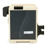
Figure 6. Fan Control Circuit Board
Heater left side panel removed

 Loading...