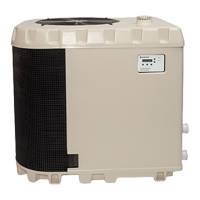
Rev. C 4/2017 ETi 400 High Efficiency Pool and Spa Heater Installation and User’s Guide
43
Fault Condition
Initial Error
Code Display
* Error Symbol/Text
(Press and disengage POOL ON
and UP arrow at the same time)
Error display will apear for 30
seconds and then previous state
will display.
Note Troubleshooting
SHORTED Stack Flue Sensors
(SFS1 or SFS2) means flue temperature is
greater than 170 F (77.7 C)
E06
SFS symbol will be displayed
All keypad disabled
(To Reset: Cycle
Power)
OPEN Stack F
lue Sensor (SFS)
E05
(error should
display after 30
sec of firing)
SFS symbol will be displayed
All keypad disabled
except OFF (To
Reset: OFF key)
OPEN Automatic Gas Shut-off Switch (AGS1
and AGS2)--opens when outlet temperature
goes above 150 F (65.5 C)
AGS1 or AGS2 symbol will be
displayed along with text “AG1” or
"AG2".
All keypad disabled
(To Reset: Cycle
Power)
Air Flow Switch (AFS1 and AFS2)
AFS symbol will be
displayed along with text “AFS”.
High Limit Switch (HLS)--Opens when
outlet temperature goes above 135 F (57.2 C)
HLS Symbol will be displayed
along with text “HLS”.
OPEN Water Pressure Switch (PS)
PS symbol will be displayed
along with text “PS”.
OPEN Water Temperature Sensor
E01
E01
LED 7 will light up
on back of board
SHORTED Water Temperature Sensor or
water tempeature greater than 125 F (51.6 C)
126
126
OPEN Condensate Float Switch
“FS” text will be displayed
Flame Sensor
IGN symbol will be displayed
along with text “IGN”
All keypad disabled
(To Reset: Cycle
Power)
Follow diagram on page 50
Follow diagram on page 50
Follow diagram on page 49
Follow diagram on page 49
Follow diagram on page 49
Follow diagram on page 49
Follow diagram on page 49
Follow diagram on page 49
Follow diagram on page 51
Follow diagram on page 47
OPEN Thermal Sensor
Symbol will be displayed
along with text “”.
Follow diagram on page 51
Section 3: Troubleshooting
Initial Troubleshooting
Only qualified, trained service technicians with appropriate test equipment should service the heater. Remember that all parts of the
system affect heater operation. Before starting this troubleshooting procedure, make sure that the pump is running correctly, that there
are no blockages in the system, that the valves are correctly set and that the time clock is correctly set and is running.
CAUTION: Installing the BLUE 120 volt plug in the control box and then connecting the heater to a
240 volt line will destroy the transformer, control broad, and ignition control module, and will void the
warranty. If you install the RED 240 volt plug and then connect the heater to a 120 volt line, the heater
READ THE FOLLOWING INFORMATION CAREFULLY
1. Check the line voltage to your heater. This heater will operate on either 120 Volts AC or 240 Volts AC.
2. Remove the covers and check the 12-pin plug in the back of the control box. The plug must match the
voltage in the heater circuit.
3. If the 12-pin plug is not plugged into the back of the control box, select the correct plug from the bag in
the control box and plug it in. The BLUE plug is for 120 volts, the RED plug is for 240 volts.
Error and Fault Codes
The following table lists the ETi 400 Heater Error and Fault Codes.
Section 3: Troubleshooting

 Loading...