PUMPS
5
Section 2
Electrical Requirements and Wiring
Electrical installation shall be in accordance with the local wiring codes taking into account its ratings. The pump is
supplied with 1.5 m (5 feet) of cord.
A GFCI (Ground Fault Circuit Interrupter) with maximum rated residual current of 30mA is
required for the power supply to the pump. Additionally, if a suitable socket outlet is not
available a weatherproof socket must be installed by an electrician in a suitable location.
GFCI tripping indicates an electrical problem. If GFCI trips and will not reset have a
qualified electrician inspect and repair electrical system.
Do not use extension leads as they are unsafe in and around the pool area.
Incorrect voltage can cause fire or seriously damage pump and voids warranty.
Voltage at pump must not be more than 6% above or 10% below motor nameplate rated
v
oltage or pump may overheat, causing overload tripping and reduced component life.
Wiring Installation
Note: B
efore installing this product, read and follow all warning notices and instructions.
Risk of electrical shock or electrocution.
The AC pump connection must be done by a service professional as described in this
manual and all applicable current local regulations. The service professional installer
should also be sure the pump motor has sufficient protection. All required pump wiring
and AC electrical information is shown on the pump's motor name plate.
BEFORE CONNECTING AC POWER WIRES TO THE PUMP, be sure to switch OFF
the main AC power supply.
PUMP GROUNDING: BE SURE TO PERMANENTLY GROUND THE PUMP MOTOR.
Be sure all electrical breakers and switches are turned off before wiring motor.
Choose a wire size from the chart below. When in doubt use a heavier gauge (larger diameter) wire.
Heavier gauge will allow the motor to run cooler and more efficient. Make sure all electrical connections are clean
and water tight. Cut wires to the appropriate length so they don’t overlap or touch when connected to the terminal
board. Connect the pump permanently to a separate circuit. Be sure no other lights or appliances are on the same
circuit.
SUPPLY WIRE SIZES (mm
2
)
(
Size and length by Power)
WATTS
15 m (50 ft.) 30 m (100 ft.) 45 m (150 ft.)
250 2.5 2.5 4.0
370 2.5 4.0 6.0
550 4.0 4.0 6.0
750 4.0 6.0 10.0
1100 6.0 6.0 10.0
HP
1/3
1/2
3/4
1
1.5
This pump is not double insulated to the water circuit.
If equipotential bonding is required by the local codes, connect all metal parts of the swimming pool, spa, or hot
tub structure, metal conduit, and metal piping in accordance with the wiring rules (AS/NZS 3000). Run a wire from
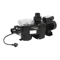
the equipotential bonding terminal on the pump to the pool bonding structure. Please see diagram below for
location of equipotential bonding terminal.
Equipotential Bonding Connection
Equipotential Bonding Terminal
 Loading...
