PUMP RE-ASSEMBLY (Continued)
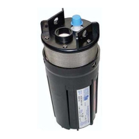
6. Install the Canister (U) (Fig. 13)
6.1 Clean the inside of the Canister with a dry cloth.
6.2 Align the wire channel in the canister with the motor lead wires.
6.3 Slide the canister over the entire assembly .
6.4 Twist the canister to align the screw holes and carefully press on
the bottom end to seat properly.
7. Install the Screws (V) (Fig. 13)
Note: DO NOT USE MORE THAN 15 ( 5) in-lb [1.7 Nm ( .5)] TORQUE
TO PREVENT STRIPPING.
7.1 Using a 3/16" Allen Wrench tighten the screws in 3 places into
the Upper Housing (N).
8. Turn the Assembly over as shown in Figure 14
9. Install the Lock Washers (Part W) and Screws (Part L) (Fig. 14)
9.1 Slide the three Lock Washers (W) onto the screws (L) and place the screws
in 3 places into the Upper Housing (N).
Note: DO NOT COMPLETELY TIGHTEN ONE SCREW AT A TIME.
TIGHTEN THE SCREWS WITH TWO PASSES,
SLOWLY COMPRESSING THE ASSEMBLY TOGETHER.
9.2 Using a 5/32" Allen Wrench tighten the screws on the first pass
with 25 ( 5) in-lb [2.8 Nm ( .5)] torque.
9.3 Tighten the screws on the second pass with 65 ( 5) in-lb [7.3 Nm ( .5)] torque.
10. Connect the Receptacle (Cable Adapter J) (Fig. 15)
Note: The orientation of the motor lead wires will not affect pump performance.
10.1 Pull the motor lead wires up through the Upper Housing (N) and insert
them into the Receptacle (Cable Adapter J).
10.2 Using a 5/64" Allen Wrench hand tighten the screws on the
Receptacle (Cable Adapter J) for both wires.
Note: DO NOT TIGHTEN WITH A POWER TOOL.
10.3 Lubricate the outer surface of the Receptacle (Cable Adapter J) with the
supplied O-Ring grease.
10.4 Match the flat side of the Receptacle (Cable Adapter J) with the flat side
of the hole in the Upper Housing (N).
10.5 Push the Receptacle (Cable Adapter J) into the hole in the Upper Housing (N)
until it is seated flush.
10.6 Spread each Receptacle (Cable Adapter J) electrical prong slightly to insure
a good electrical connection.
FIGURE 12
V
UPPER HOUSING
U
MOTOR LEAD
WIRES
 Loading...
