7 SHURFLO WATER BOOST MODULAR FILTRATION SYSTEM INSTALLATION AND OPERATION GUIDE
SYSTEM STARTUP AND OPERATIONS CONTINUED
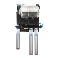
Plumbing Procedure
Please refer to the image below, as reference is made throughout this procedure to these components.
Main City
Water Inlet
Ice Maker
Water Supply*
*Ice Maker Water Supply is non-boosted/non-filtered
Water Out
Non-Carb System
Water Out
to Carbonator
WBMF System Out
Ball Valve
3
Filter Head
Assembly
4
Bypass
Plug/Cap
5
Filter Canister
stainless steel sump
6
Filtered Water
Pressure Gauge
7
Purge Valve
w/o drain tubing
attached
8
Booster Pump
(behind shroud)
9
Tank Pre-charge
Valve and Cap
10
Pressure Relief
Valve
2
City Water In
Ball Valve
1
Ice Filter Canister
stainless steel sump
11
1. Position both inlet and outlet globe-valves to the
off position.
2. Connect incoming city water supply line to inlet
shut-off valve.
If icemaker is being installed, follow steps 3 and 4.
If icemaker is not being installed, proceed to step 5.
3. Remove plugged icemaker supply from line inlet
globe-valve.
4. Connect icemaker supply line to the inlet globe-valve.
5. Connect carbonator supply line to outlet globe-valve.
If installing non-carbonated valves on dispense unit
follow steps 6 and 7.
If non-carbonated valves are not being installed,
proceed to step 8.
6. Remove plugged non-carbonated supply line from outlet
of globe-valve.
7. Connect non-carbonated supply line to outlet of
globe-valve.
8. Install inline water pressure reducer valve just prior to the
inlet fitting of the carbonator pump.
Pentair
®
Shurflo
®
inline water pressure reducer valves
are recommended for all water boost modular system
installations. For additional information regarding the water
pressure reducer valve please refer to Pentair Shurflo
document 911-380.
9. Turn the purge valve to the off position.
10. Check pre-charge pressure of accumulator tank for
proper pressure – add additional pressure if required
using air only (do not pre charge accumulator with CO
2
).
50 psi pre-charge pressure is recommended for carbonated
beverage installations.
11. Manually open and close pressure relief safety checking
for proper functioning.
12. Uncoil purge line and put into bucket or drain.
13. Turn on incoming city water supply and inlet globe-valve.
14. Outlet globe-valve should still be in the off position.
Inspect properly connected water supply line to icemaker.
15. Connect power supply to water boost pump.
16. Turn the purge valve to the open position.
17. Purge system until all air is evacuated and a steady water
flow is present.
18. Turn purge valve to the off position.
19. Recoil and secure purge line to system.
20. Allow water boost pump to cycle off
Please follow all Beverage OEM standard startup procedures
for carbonated system applications.
21. Check system for water leaks.
22. Turn the outlet globe-valve to the on position.
23. Check for proper operation of icemaker, carbonator and
non-carbonated dispense valve operation.
(continued)
 Loading...