7
S536 (11-25-19)
ELECTRICAL
3. Ground the pump permanently using a wire of the same size as
that specified in this section’s Wiring Chart. Make ground
connection to green grounding terminal under motor canopy
marked GRD. or .
4. Connect ground wire to a grounded lead in the service panel or to
a metal underground water pipe or well casing at least 10 feet long.
Do not connect to plastic pipe or insulated fittings.
5. Protect current carrying and grounding conductors from cuts,
grease, heat, oil, and chemicals.
6. Connect current carrying conductors to terminals L1 and L2
under motor canopy. When replacing motor, check wiring diagram
on motor nameplate against Figure 7 and 8. If the motor wiring
diagram does not match either diagram in Figure 7 and 8, follow
the diagram on the motor.
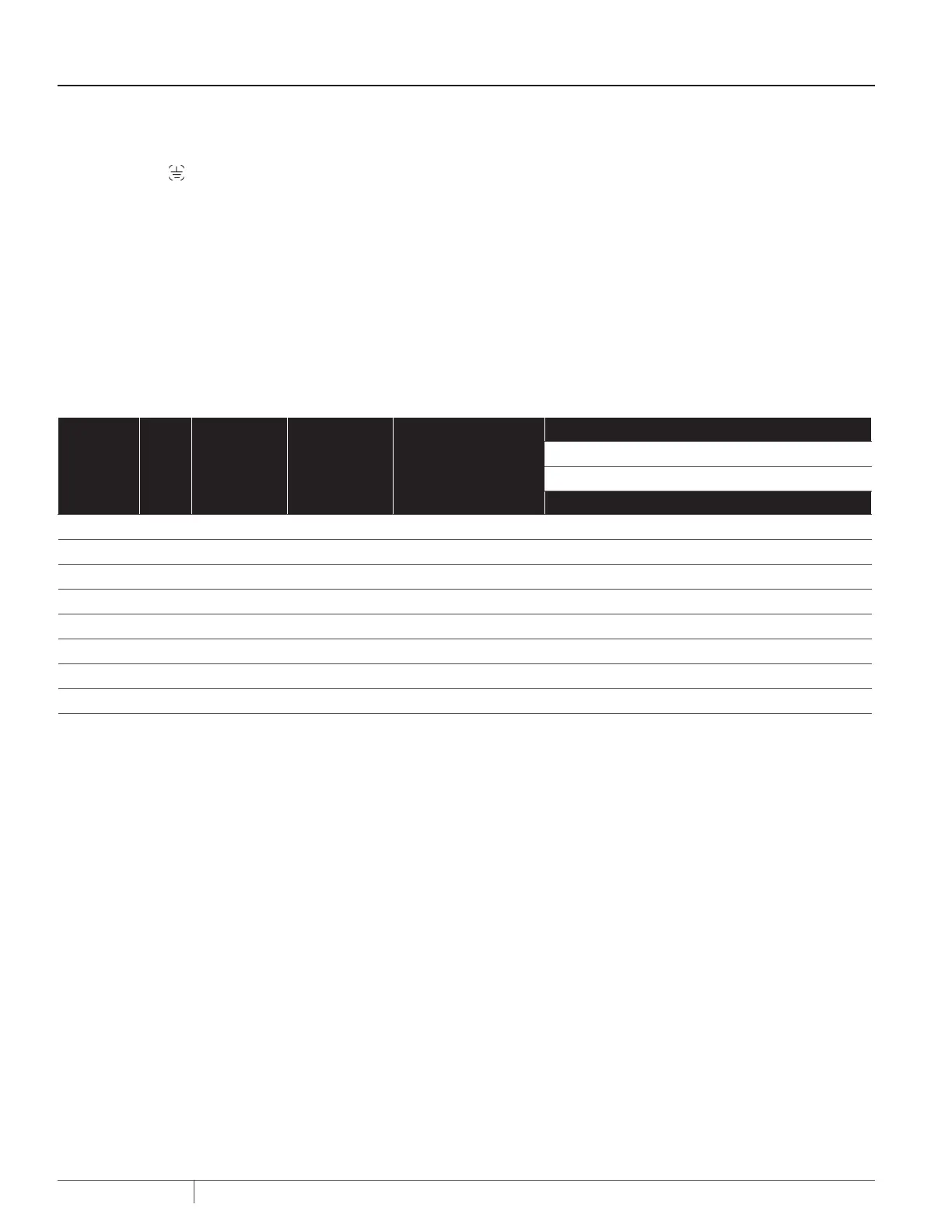
Wiring Chart – Recommended Wire and Fuse Sizes
MODEL HP MAX. LOAD AMP VOLTS/HZ PHASE BRANCH FUSE RATING AMP
DISTANCE IN FEET (METERS) FROM MOTOR SUPPLY
0 - 50 51 - 100 101 - 200 201 - 300
(0 - 15) (31 - 61) (62 - 91) (92 - 122)
AWG WIRE SIZE (mm
2
)
DS3HE-01 1 14.8/7.4 115/230/60/1 20/15 12/14 (3/2) 12/14 (3/2) 8/14 (8.4/2 6/14 (14/2)
DS3HE3-01 1 3.6/1.8 230/460/60/3 20/15 14/14 (2/2) 14/14 (2/2) 14/14 (2/2) 14/14 (2/2)
DS3HF-01 1-1/2 20/10 115/230/60/1 25/15 10/14 (5.5/2) 10/14 (5.5/2) 8/14 (8.4/2) 6/12 (14/3)
DS3HF3-01 1-1/2 4.7/2.35 230/460/60/3 15/15 14/14 (2/2) 14/14 (2/2) 14/14 (2/2) 14/14 (2/2)
DS3HG-01 2 24/12 115/230/60/1 30/15 12/14 (3/2) 10/14 (5.5/2) 6/14 (14/2) 6/12 (14/3)
DS3HG3-01 2 5.8/2.9 230/460/60/3 15/15 14/14 (2/2) 14/14 (2/2) 14/14 (2/2) 14/14 (2/2)
DS3HHG-01 2-1/2 24/12 115/230/60/1 30/15 12/14 (3/2) 10/14 (5.5/2) 6/14 (14/2) 6/12 (14/3)
DS3HHG3-01 2-1/2 6.9/3.45 230/460/60/3 15/15 14/14 (2/2) 14/14 (2/2) 14/14 (2/2) 14/14 (2/2)

 Loading...