186
[Disassembly & Assembly procedures]
Outline
The disassembly and assembly procedures of MZ-7 are similar to the MZ-5 and MZ-10.
The only exclusive notice of assembly for MZ-7 is mentioned below.
For others, refer to the Service manual of MZ-5 and MZ-10.
1. Cosmetic parts
[Disassembly procedures]
1-1.
Flash pop-up
To remove the top cover, insert the battery and push the flash pop-up button.
In case of the power line of the camera is defected, use the hand-made tool to pop-up the
flash
1-2.
Bottom cover (A401), Back cover
7 screws (A181, A187 x6), Battery cover (0-A402)
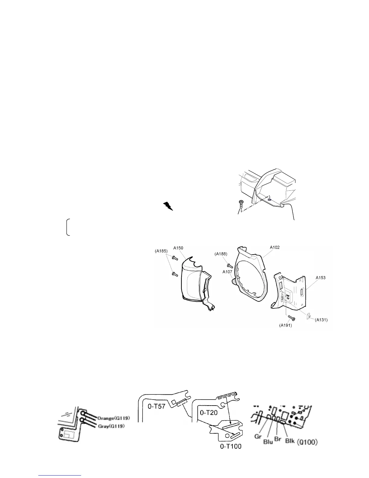
1-3. Top cover (0-A301) and Front cover
1) 8 screws for top cover
A186, A187 x2, A188 x2, A190,
TY-CNL-D 1.7x8.0(Ni), TY-CNL-D1.7x8.0
2) Discharging the Main capacitor
Lift up the top cover slightly and discharge.
The blue lead wire (Xe+) on Flash PCB
The bayonet mount retainer screw (GND)
3) Front cover (A102, A153), Grip (A150)
[Note for assembly]
Set Focus mode lever (A131)
and AF-SW at “AF” position.
*In case of replacing A131(=27250-A131),
cut the positioning stud of reverse side
of A131. (Early production model)
4) Unsolder 7 lead wires and 3 FPC (T51, 0-T20, 0-T57) come from
top cover
[Note of assembly]
1)
Solder wires and FPC in order of Orange and Yellow (G119), T51, 0-T20, 0-T57,
Black (A330) and lead wires from Q100
2)
Arrange lead wires of Q100 (Green, Blue, Brown, and Black) and Black (A330).
(Same as MZ-10)
3
)
Install A186 screw before retract the flash.
①
②
 Loading...