27550 3/9
DT(3x7)
Red
(A36)
Blk
(A37)
2 lands
(I210)
Ye
(C18)
Br
(0-S200)
Pu
(C18)
R
(A35)
Pi
(0-S200)
2 lands
4 lands
(0-Q201)
Gray
(0-Q201)
DT(10x6)
2. Soldering of Main body
[Disassembly procedure]
2-1. Switch the panorama lever to “Full frame”
2-2. Remove the LCD….TY-CNL-D1.7x5.0
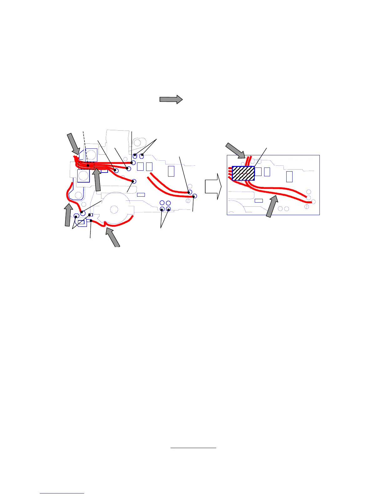
2-3. Around the release SW (Refer to the figure below)
8 lead wires, 8 soldering lands
[Note of assembly]
Arrange lead wires as below. ( )
2-4. Top of the film chamber
[Note of assembly]
Position the FPC at correct place and fix with DT (4x10).
2-5. Soldering
2 lead wires of N300 (Red and Black, Unsolder at FPC of G100).
Soldering lands : 4 FPC (T81, T301, T61, T64), DX contact (R110)
[Note of assembly] After soldering, put T81 FPC aside of mirror box.
2-6. Base plate (O205)
1) Battery contact piece (-) (A34)
3)
TY-CNL-D1.7x4.0, Lift up O205.
2-7. Eyepiece frame (M301)
2 screws
2-8. Main body and Front housing
6 screws, A162
[Note of assembly]
While paying attention to the lead wires and FPC, install the Front housing with the Main body.
The Mechanical back (Standard : 45.46 mm
±
0.02 (Same as MZ-5)
 Loading...