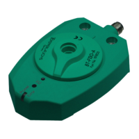
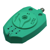
PMI360DV-F130-IU2E2-V15
Installation
2015-06
13
5.3 Electrical connection
Wire the electrical connections on the sensor as follows:
Electrical connection
1. For the electrical connection to the sensor, use one of the cordsets with a 5-pin connector
M12 x 1 listed in the Accessories chapter.
2. When routing the electric cables, make sure they are protected against physical damage.
3. Make sure that cables are routed at a sufficient distance from other current-carrying system
components. This is the only way to guarantee adequate protection from short circuits
and/or interfering signals. If required shielded cables can be used to help prevent electrical
interference.
4. Check that the wires are connected correctly before connecting the cordset to the sensor.
On Pepperl+Fuchs cordsets, the wire colors are assigned to the connecting pins in the
connector according to DIN EN 60947-5-2.
5. Attach the socket on the cordset to the connector on the sensor and tighten the union nut by
hand.
6. Switch on the operating voltage.
The "Power/Error" LED on the sensor lights up green if the actuator is already fitted and
red if the actuator is not yet fitted.
Wire colors are assigned to the connecting pins in the connector according to DIN
EN60947-5-2.
Note!
Other LEDs may light up depending on the position of the actuator.
Connector pin Function
1 +U
B
2 Switching output Q2 (detection zone S2)
3 -U
B
4 Switching output Q1 (detection zone S1)
5 Analog output I/U
Connecting pin Wire color
1 brown
2 white
3 blue
4 black
5 gray
 Loading...