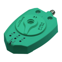
PMI360DV-F130-IU2E2-V15
Commissioning
2015-06
15
Programming switching output S2
The switching output 2 (S2) is programmed in the same way. Press the S2 button. The S2 LED
indicates the status.
6.2 Programming the analog output
The start point of the analog output is preset to the angular position 0° and the end point is
preset to the angular position 360°in the factory. If the actuator is located in the 0° position, a
current value of 4 mA or a voltage value of 0 V is available at the analog output depending on
the connected load. If the actuator is rotating clockwise, the output value increases
proportionately according to the angle until the analog output adopts the maximum value of 20
mA or 10 V after reaching the angular position 360°. The start and end points of the analog
output can be programmed at any desired position. The permitted limited values of the angle
range for the analog output are 45° and 360°.
Program the analog output as follows:
Programming the analog output
1. Make sure that the sensor is mounted correctly and securely, and check that an actuator with
the specified dimensions is positioned at the correct distance from the surface of the sensor.
See chapter 5.2
2. Press the "I/U" button for 2 s.
The flashing yellow LED indicates that the device is ready for you to teach in the start
point of the analog ramp.
3. Move the actuator to the position that you wish to define as the start point of the analog
ramp and then press the "I/U" button.
The yellow "I/U" LED lights up for 2 seconds and then starts to flash again. This indicates
that the device is ready for you to teach in the end point of the analog ramp.
4. Move the actuator to the position that you wish to define as the end point of the analog
ramp.
When the actuator rotates, the first 30° define the direction of rotation of the
measurement range in which the values of the analog output increase
(clockwise/counterclockwise). If the actuator rotates less than 30°, the previously
set direction of rotation is retained.
5. Briefly press the "I/U" button.
The setting is then stored in the non-volatile memory of the sensor. The yellow "I/U" LED
then lights up permanently to indicate that programming was successful.
When the actuator moves in a clockwise or counterclockwise direction, the analog output value
increases starting from the programmed start position, depending on the direction in which the
actuator moves during the programming process. The overall signal range 4 … 20 mA or 0 ...
10 V of the analog output is scaled to the programmed angle segment.
Note!
Activating the keylock
The keylock is not activated initially. Press any button on the sensor briefly to determine
whether the keylock is active. If the color of the "Power/Error" LED remains green, the keylock
is inactive and if the color of the "Power/Error" LED changes to red, the keylock is active. To
activate the keylock, press and hold the S1 and S2 keys simultaneously for 3 seconds. The
color of the "Power/Error" LED changes to red.
Note!
A loss of the actuator during the programming process interrupts the programming process
and a fault message is issued. The last valid parameters are retained.

 Loading...