Why can't the buttons unlock on my Pepperl+Fuchs Measuring Instruments?
- JJames MunozSep 12, 2025
The buttons might not unlock because buttons S1 and S2 were not pressed long enough. Press the buttons for about 3 seconds to unlock them.

Why can't the buttons unlock on my Pepperl+Fuchs Measuring Instruments?
The buttons might not unlock because buttons S1 and S2 were not pressed long enough. Press the buttons for about 3 seconds to unlock them.
Why does the 'Power/Error' LED light up red permanently or intermittently on Pepperl+Fuchs PMI360DV-F130-IU2E2-V15?
The 'Power/Error' LED might light up red because there is no actuator in the sensor's detection area, or the actuator detection is unreliable. Ensure the actuator is correctly mounted or install one with the correct dimensions at the appropriate distance from the sensor.
What to do if analog current output yields a value of approximately 3.6 mA on Pepperl+Fuchs PMI360DV-F130-IU2E2-V15?
If the analog current output shows about 3.6 mA, it could be due to: * No actuator being in the sensor's detection area, or unreliable detection of the actuator. Make sure the actuator is correctly mounted, or install a suitable actuator at the right distance. * The actuator being outside the parameterized measurement range. Verify the position of the parameterized measurement range is correct.
What to do if the analog output does not reach the maximum value on Pepperl+Fuchs Measuring Instruments?
If the analog output doesn't reach its maximum value, the sensor's operating voltage might be too low, or the load impedance might be out of specification. Check the sensor's operating voltage and ensure the load impedance is within the specified limits.
What to do if the switching output signal 'chatters' on Pepperl+Fuchs Measuring Instruments?
If the switching output signal 'chatters', it might be due to using a different actuator with incorrect dimensions or an incorrect distance to the sensor. Install an actuator according to specifications.
What to do if the output signal is unstable or unreliable on Pepperl+Fuchs Measuring Instruments?
If the output signal is unstable or unreliable, the actuator might be rotating too quickly. Ensure the actuator's speed is no more than 100 rotations per minute.
Why does the function of the output/outputs remain unchanged after programming my Pepperl+Fuchs PMI360DV-F130-IU2E2-V15 Measuring Instruments?
If the output function remains unchanged after programming, it could be because the programming process wasn't completed within the 1-minute timeframe, or the wrong button was pressed. Complete the programming process by pressing the corresponding button for the output a third time within the time frame.
Why can't I move the sensor in programming mode on my Pepperl+Fuchs Measuring Instruments ('Power/Error' LED lights up red)?
If you cannot move the sensor in programming mode and the 'Power/Error' LED lights up red, it may be because no actuator is available, or your own actuator is mounted too far from the sensor's surface. Mount the actuator according to the specifications.
Why can't I move the sensor in programming mode on my Pepperl+Fuchs Measuring Instruments (relevant yellow LED does not flash when a button is pressed)?
If you can't move the sensor in programming mode and the yellow LED doesn't flash when you press a button, you probably aren't pressing the button long enough. Press the button for programming the output for about 2 seconds.
Why can't I move the sensor in programming mode on my Pepperl+Fuchs PMI360DV-F130-IU2E2-V15 Measuring Instruments, and the 'Power/Error' LED lights up red when a button is pressed?
If you can't move the sensor in programming mode and the 'Power/Error' LED lights up red when a button is pressed, the keylock is likely activated. Unlock the buttons.
| Sensing range | 360 ° |
|---|---|
| Shaft Type | Solid shaft |
| Shaft Diameter | 6 mm |
| Resolution | 0.1° |
| Housing material | Aluminum |
| Protection class | IP67 |
| Supply voltage | 10 ... 30 V DC |
| Connection | M12 connector |
| Measuring Range | 360° |
| Power Supply | 10 to 30 V DC |
| Operating Temperature | -20 to +70 °C |
Explains symbols used in the manual for important information and handling instructions.
Provides contact details for Pepperl+Fuchs GmbH for inquiries about the device.
States product compliance with European standards and guidelines; notes on obtaining Declaration of Conformity.
Details safety-relevant symbols (Danger, Warning, Caution) and informative symbols (Note, Action).
Describes the product's purpose for non-contact angle position detection on valve actuators and valves.
Outlines responsibilities for installation, operation, and maintenance by trained personnel.
Advises on proper disposal of electronic waste according to local regulations.
Explains the system's function for non-contact angular position detection and rotary movement feedback.
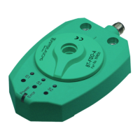
Details the LED indicators and programming buttons on the device for status and configuration.
Lists the items included in the product's delivery package.
Lists available connecting cables with different connector types, materials, lengths, and order designations.
Describes the BT-F130-A actuator for mounting on drive shafts or servodrives.
Warns about risks of short circuits and damage when working with live parts during installation.
Provides step-by-step instructions for securely mounting the sensor and actuator.
Details dimensions and material requirements for alternative actuators.
Explains how to wire the electrical connections to the sensor using cordsets.
Details how to program the two switching zones for the sensor's outputs.
Explains how to program the start and end points of the analog output signal.
Illustrates the output function based on actuator position and programming methods with a diagram.
Describes how switching outputs activate based on actuator position within programmed zones.
Explains analog output behavior for voltage and current based on load and actuator position.
States that regular adjustment is not necessary, but checks for secure attachment are recommended.
Details the procedure for resetting individual output functions to their default settings.
Provides a table of common issues and solutions for output programming problems.
Lists errors, possible causes, and actions for rectifying malfunctions during device operation.
Advises adherence to current statutory and local regulations for disposing of electronic waste.