A
Andrew HardySep 7, 2025
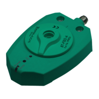
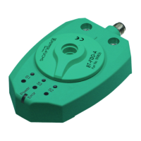
Why does the 'Power/Error' LED light up red during programming of Pepperl+Fuchs PMI360DV-F130-IU2E2-V15?
- JJake GriffithSep 8, 2025
If the 'Power/Error' LED lights up red during programming, it could be that the actuator was lost during the parameterization process, or the distance between the actuator and the sensor surface is too great (if using your own actuator). Ensure the concentricity and adjustment of your actuator doesn't lead to it being lost.