PMI360DV-F130-IU2E2-V15
Product Description
2015-06
9
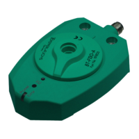
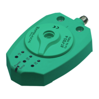
4.2 Displays and controls
4 LEDs and 3 programming buttons are located on top of the PMI360DV-F130-IU2E2-V15.
The central, front "Power/Error" LED is a 2-color LED that lights up or flashes green (normal
operation) or red (fault) depending on the operating state of the device. The LEDs "S1", "S2"
and "I/U" are yellow and indicate the status of the device during programming and normal
operation.
The programming buttons are used to configure the angular positioning system. The central I/U
button is used to configure the start and end points of the analog output and the outer "S1" and
"S2" buttons are used to configure the start and end of the detection zone of the two switching
outputs on the sensor.
The "S1", "S2" and "I/U" LEDs correspond to the "S1", "S2" and "I/U" programming buttons.
4.3 Delivery package
■
PMI360DV-F130-IU2E2-V15
■
Quick start guide
Note!
In principle, the actuator BT-F130-A is not required. A damping element made from
construction steel such as S235JR+AR or international equivalent, (previously St37-2) can be
mounted on the rotary system component. This damping element must fulfill all requirements
relating to the material, dimensions and distances to the inductive angular positioning system
PMI360DV-F130... See chapter 5.2
ALED indicators
B Programming buttons
B
A
 Loading...