Assembly and adjustments (continued)
Install a table insert (Fig. 12)
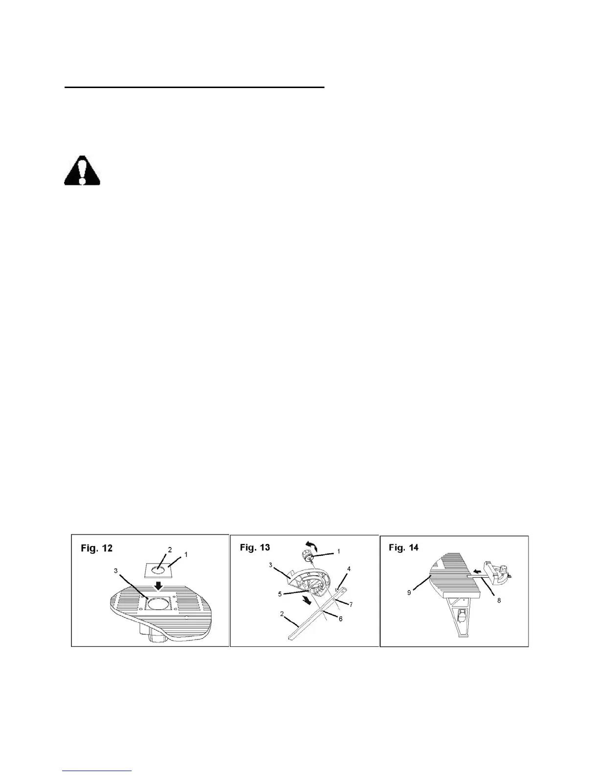
Three table inserts, each with a different size opening, are supplied with the router table. Change
the table inserts as needed to accommodate the size of the router bit. The bit should not make
contact with the table insert.
WARNING: Do not use the router dust collecting attachment when installing the router
on the router table.
1. Select a table insert (1) that has a clearance hole (2) that is larger than the diameter of the bit
you will be using.
2. Align the table insert with the square depression (3) that surrounds the router opening in the
table.
3. Press gently and evenly on the table insert to secure it in the depression.
Assemble the miter gauge (Fig. 13–14)
The miter gauge pivots on the miter bar and is secured in position by a lock knob that fits into a
threaded opening on the bar. The small post on the bottom of the miter gauge fits into an
unthreaded opening on the bar.
1. Remove the lock knob (1) from the miter bar (2).
2. Slide the front of the miter gauge (3) under the pointer (4) on the miter bar.
3. Insert the small post (5) on the bottom of the miter gauge into the unthreaded hole (6) on the bar.
4. Insert and tighten the lock knob bolt through the miter gauge and into the threaded hole (7) on
the miter bar.
5. Place the assembled miter bar (8) into the channel (9) that runs the full length of the table. The
bar should move freely in this channel.
Adjust the miter gauge
To change the angle of the miter gauge, loosen the lock knob and move the gauge to the desired
angle. Tighten the lock knob to maintain the gauge at the selected position.
16