13
1.10
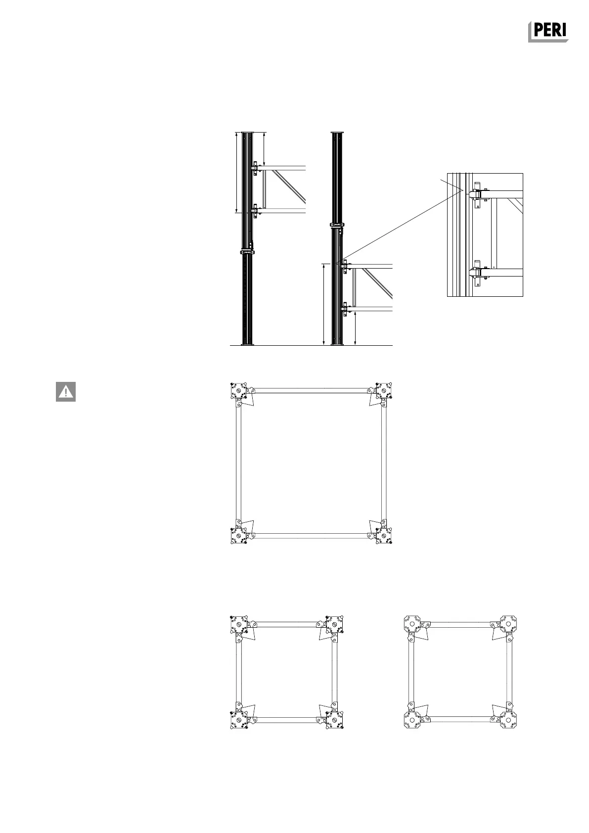
950
950
400
400
MULTIPROP System
Instructions for Assembly and Use – Standard Configuration
A2 MULTIPROP System
Only wedge connections of the same
colour are permissible at a connection
point!
(Fig. A2.08)
When inserted, the wedges (2.3) of
the wedge connections must always
be pointed downwards so that any
self-actuating loosening is not
possible!
Application of Frames ≤ MRK 90
The Frames ≤ MRK 90 must be in a
counter position on the inner tube as
mounted on the outer tube. Thus the
colour of the wedge connections on
the tube changes over the height of
the tower.
(Fig. A2.09a + A2.09b)
Arrangement of the Frames MRK
Universally valid
The arrangement of the Frames MRK is
shown in the relevant diagram contained
in the type test.
Markings on the outer tube
Arrange the Frames MRK at the circu-
lar-shaped recesses (1.10) of the outer
tube. This results in a distance of 40 cm
to the base plate.
(Fig. B2.07a + B2.07b)
Fig. A2.09a
yellow
silver
yellow
yellow
silver
yellow
silver silver
silver silver
yellow yellow
Fig. A2.08
Outer tube + inner tube
Outer tube top Outer tube bottom
Outer Tube ≤ MRK 90 Inner Tube ≤ MRK 90
Fig. A2.09b
Fig. A2.07a
Fig. A2.07b
AuV MULTIPROP EX.indb 13 07.01.16 11:55