PART 4: CONTROLS AND DISPLAYS
PB1319 (CAT. NO. 5296 ) —33— 22-01691 (R02/02)
• the speed of the blowers
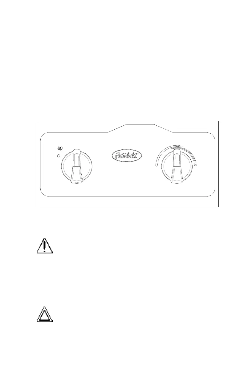
The system’s controls are mounted in the header in front of the driver.
They include the following (see illustration below):
• A rotary knob to operate the modulating water valve (for air tem-
perature control), located in the heater control head.
• A rotary switch to select blower speed, located in the heater con-
trol head.
• A switch to select either fresh air or recirculated cab air as blower
feed air.
• A switch to select cab interior or defrost vents for heated air output.
• To heat the cab, select the "Cab” mode and the desired air
source, then adjust the air temperature lever and blower speed
until comfortable.
WARNING! Do not drive with visibility reduced by fog, con-
densation, or frost on the windshield. Your view may be
obscured, which could result in an injury accident. For
clear visibility and safe driving it is extremely important for
you to follow the instructions pertaining to the function and
use of the ventilation/heating and defogging/defrosting
system. If in doubt, consult your dealer. Maximum heating
output and fast defrosting can be obtained only after the
engine has reached operating temperature.
CAUTION: During extreme cold weather, do not blow hot
defroster air onto cold windshields. This could crack the
glass. Turn the air flow control lever to Defrost and adjust
the fan speed accordingly while the engine warms. If the
engine is already warm, move the temperature selector to
Cool, then gradually increase the temperature when you
see that the windshield is starting to warm up.
03032
1
2
4
3