Adjustment
12
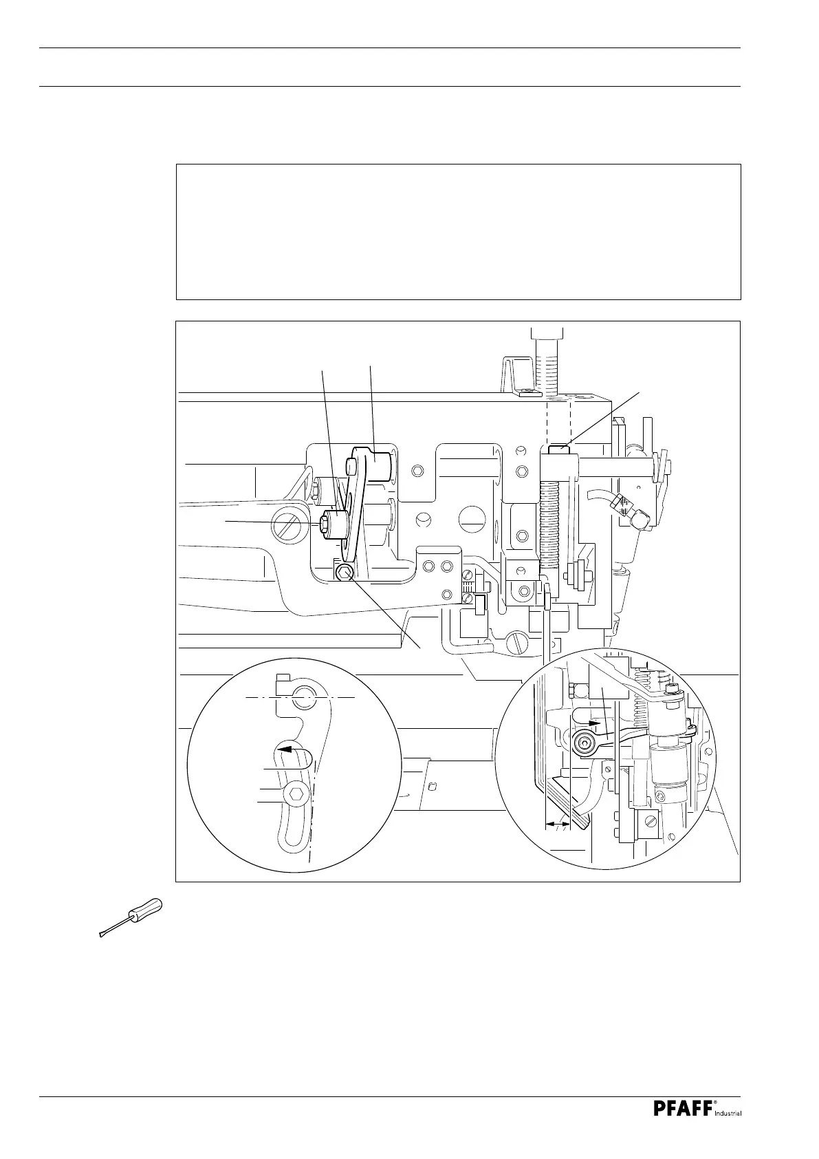
13.04.07 Home position of roller presser drive
Rule
1. The clamping surfaces of the lever 1 in the front turning point position should be
horizontal with maximum stitch length regulation.
2. The lever 3 should be in the centre of the cutout in the lever 1.
3. The lever 5 should have a clearance of 8 mm ( model N8 ) to the side cover at its rear
turning point.
Fig. 13 - 07
O Set the maximum stitch length.
O Turn the lever 1 ( screw 2 ) according to rule 1.
O Turn the lever 3 ( screw 4 ) according to rule 2.
O Turn the lever 5 ( screw 6, accessible from the top through the hole in the housing ) ac-
cording to rule 3.
1
6
3
4
2
5
8 mm
 Loading...