Adjustment
24
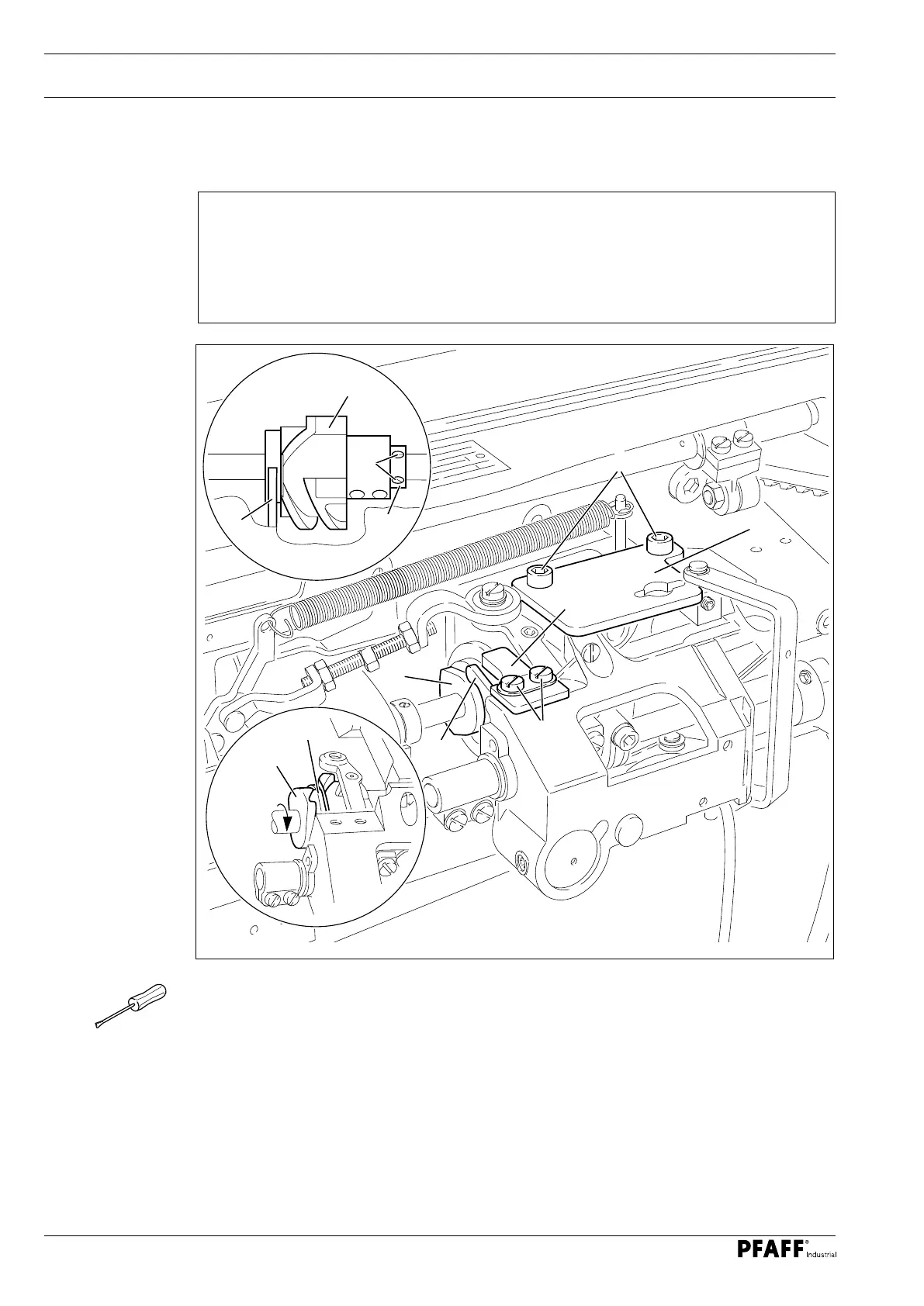
13.05 Adjusting thread trimmer -900/56
13
.05.01 Control cam ( pre-calibrating )
O Remove the catch 1 ( screws 2 ).
O Remove the plate 3 ( screws 4 ).
O Loosen the four screws of the control cam 5 and the screws 6 of the retaining collar 7.
O Move the control cam 5 sideways according to rule 1.
O Adjust the retaining collar 7 in this position so that it touches the control cam 5 and
tighten the screws 6.
O Move the thread lever to t.d.c. by turning the handwheel.
O Turn the control cam 5 in the direction of rotation according to rule 2, ensuring that it
rests on the retaining collar 7.
O Tighten the four screws of the control cam 5 in this position.
Fig. 13 - 19
Rule
1. The bearing surface of the control cam 5 should be positioned centrally to the pawl
8 on the side.
2. When the thread lever is at t.d.c., the start of the largest eccentricity of the bear-
ing surface ( in the direction of rotation ) should be under the tip of the pawl 8.
8
5
7
6
5
8
4
3
1
8
5
2
 Loading...