12
Adjustment
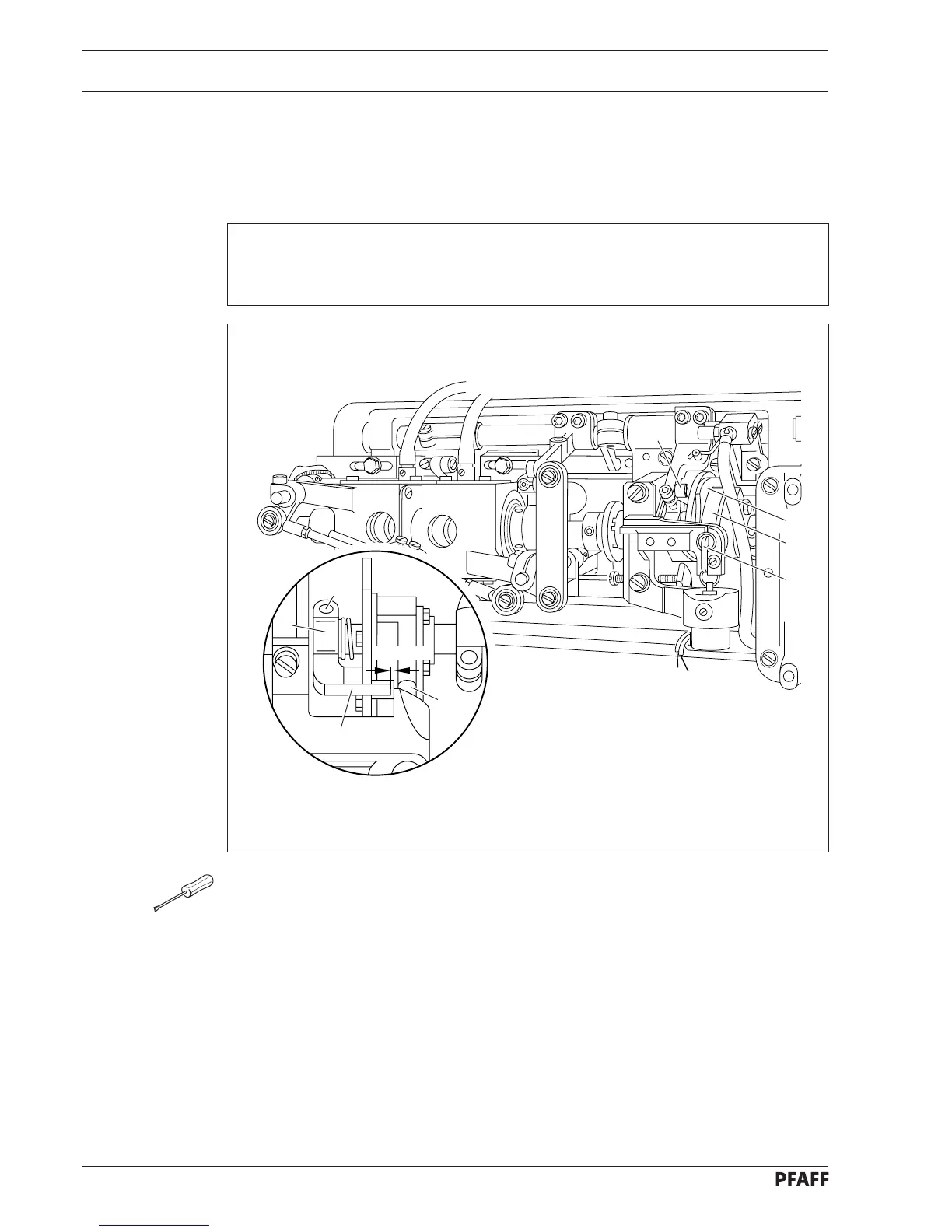
7 Control cam and locking bracket
7.01 Axial position of crank lever
● Turn balance wheel in feeding direction until needle bar is positioned 10 mm before b.d.c.
● Loosen screw 1 just sufficiently for crank lever 2 to be moved on its shaft against
resistance.
● Operate engaging lever 3.
● Continue turning balance wheel until control pin 4 has set control cam 5 at its left point of
reversal.
● Retain this position, then move crank lever 2 laterally according to the requirement.
● Turn balance wheel in feeding direction until needle bar is positioned 10 mm before b.d.c.
● Tighten screw 1.
● Make sure control cam 5 is just about to snap back to starting position, then push it all
way to left. As you continue turning balance wheel, return motion cam 6 must freely pass
stud 7.
If required, repeat solenoid bracket adjustments (chap.4).
7
6
5
3
1
2
8
4
0.2 mm
Requirement
Operate engaging lever 3 and turn the balance wheel to set control cam 5 at its far left
position; there must then be a clearance of 0.2 mm between guide finger 8 and bottom of
the control cam cutout (see below).