14
Adjustment
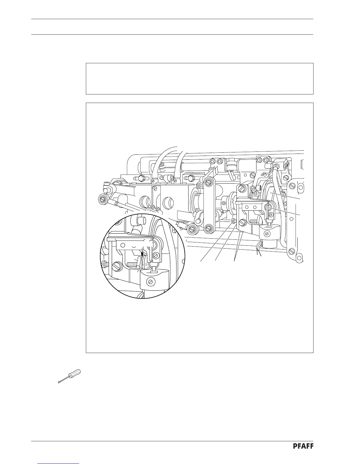
7.03 Locking bracket
➤
➤
➤
3
4
2
65
1
4
0.5 mm
● Turn balance wheel in feeding direction until needle bar is positioned 10 mm before b.d.c.
● Operate engaging lever 1.
● Continue turning balance wheel in feeding direction until needle bar is positioned at t.d.c.
● Loosen screws 2 on locking bracket 3.
● Push control cam 4 all way to left by hand.
● Retaining this position, set clearance between control cam 4 and locking
bracket 3 according to the requirement.
● Tighten screws 2.
● Loosen nut 5 and bring screw 6 into contact with locking bracket 3.
● Tighten nut 5.
● Check this adjustment according to the requirement.
Requirement
With control cam 4 guided to the left and pushed to the left by hand and the needle bar at
t.d.c. there must be a clearance of 0.5 mm between locking bracket 3 and control cam 4.