7
Adjustment
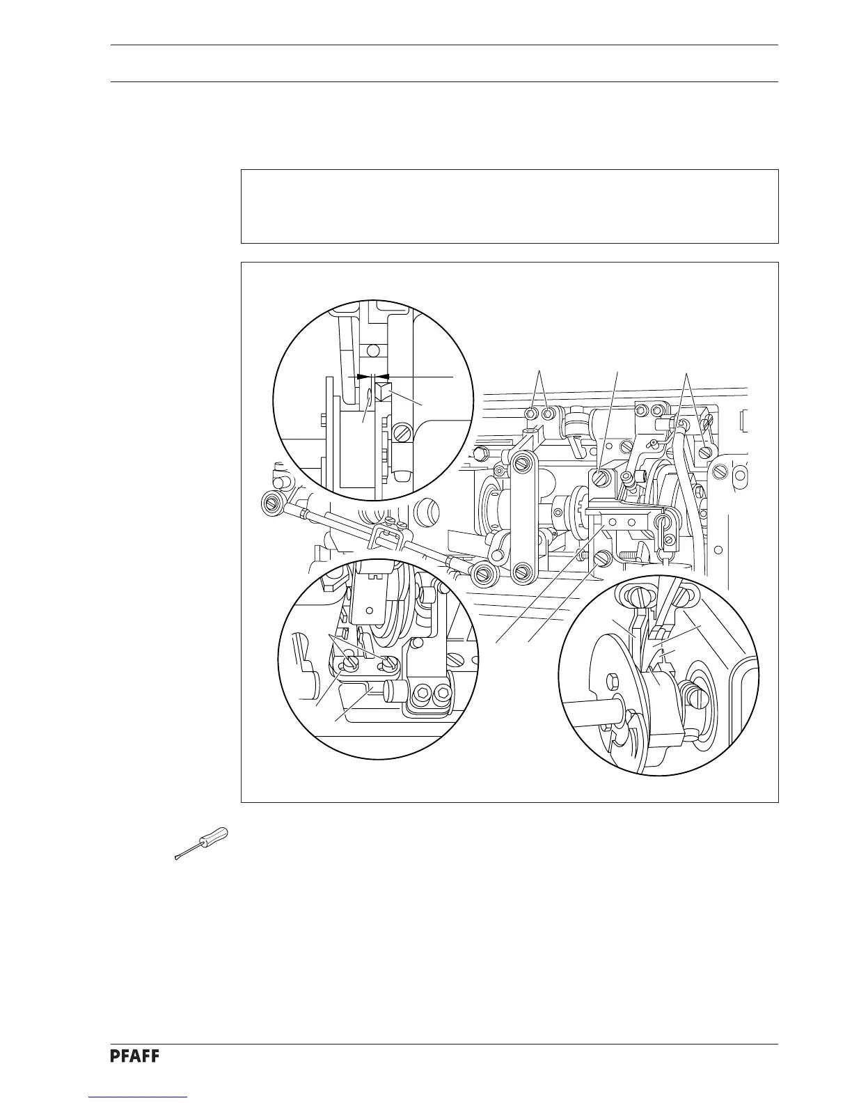
3 Tension release trip
6
3
9
7
2
4
3
2
1
1 mm
● Remove solenoid bracket 1 (screws 2)
● Loosen screws 3 and for more extensive adjustments, also screws 4.
● Turn balance wheel until the widest part of trip 5 is aligned with tension release trip 6.
● Adjust lateral position of stop finger 7 according to the requirement.
● In this position, make sure that stop finger 7 is in contact with bracket 8, move bracket 9
of release trip fully to left in elongated hole and tighten both screws 3.
● Check this adjustment according to the requirement.
● If more extensive adjustments are to be made, screws 4 should remain loose until the
catcher actuating lever is adjusted.
● For adjusting the solenoid bracket 1 only lightly tighten screws 2 (chap. 4).
5
7
5
8
6
Requirement
When the broadest partof trip 5 is aligned with tension trip 6, with the control cam in
resting position and the presser foot lowered, there must be a clearance of roughly 1 mm
between the left side of trip 5 and tension release trip 6.