9
Adjustment
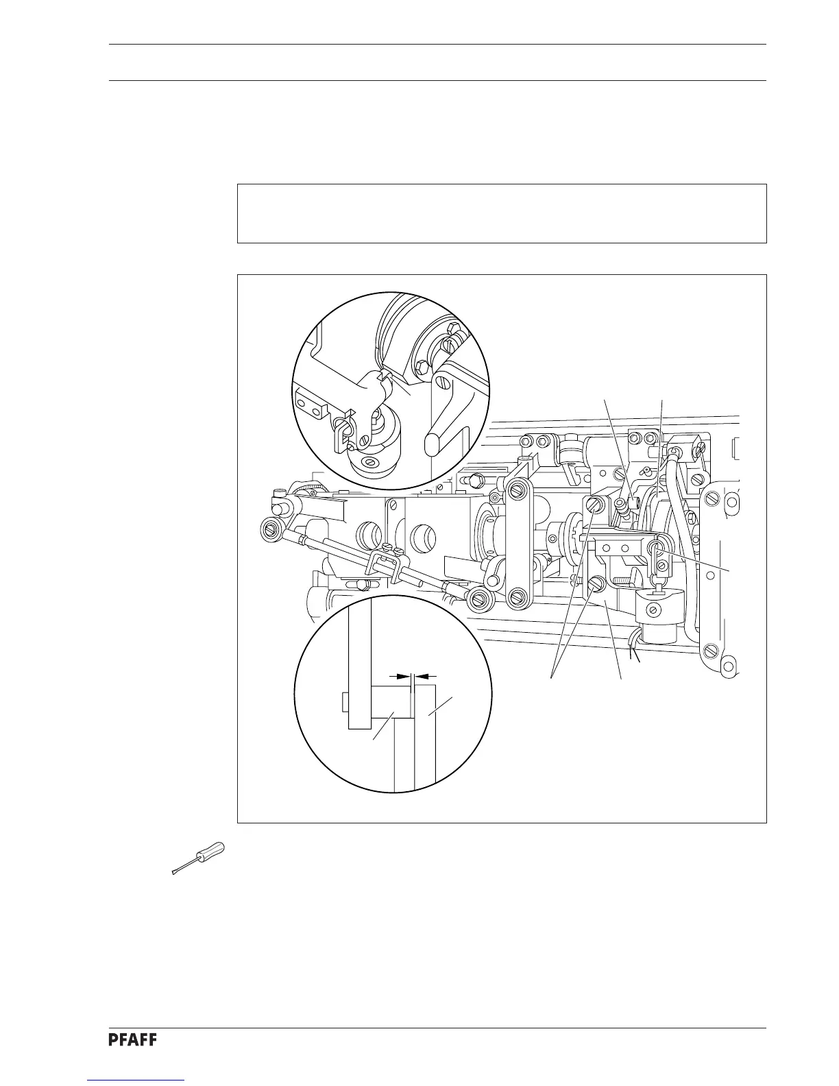
4.02 Solenoid bracket on -900/61
● Turn balance wheel in feeding direction until needle bar is positioned 10 mm before b.d.c.
● Operate engaging lever 1.
● Continue turning balance wheel until control pin 2 is positioned opposite return motion
cam 3.
● Loosen screws 4.
● Adjust position of solenoid bracket 5 according to the requirement.
● In this position, tighten screws 4.
● Check this adjustment according to the requirement.
● Turn balance wheel opposite feeding direction until control pin 6 is retained.
3
2
4
6
2
3
5
0.5 mm
1
Requirement
With engaging lever 1 operated, and control pin 2 positioned beside return motion cam 3,
there must be a clearance of 0.5 mm between control pin 2 and return motion cam 3.