Operating Manual DTS and DTI 6201C / 6301C Multi-Controller (MC) 086100014 © Pfannenberg GmbH Page 21 / 43
3.5 Electrical connection
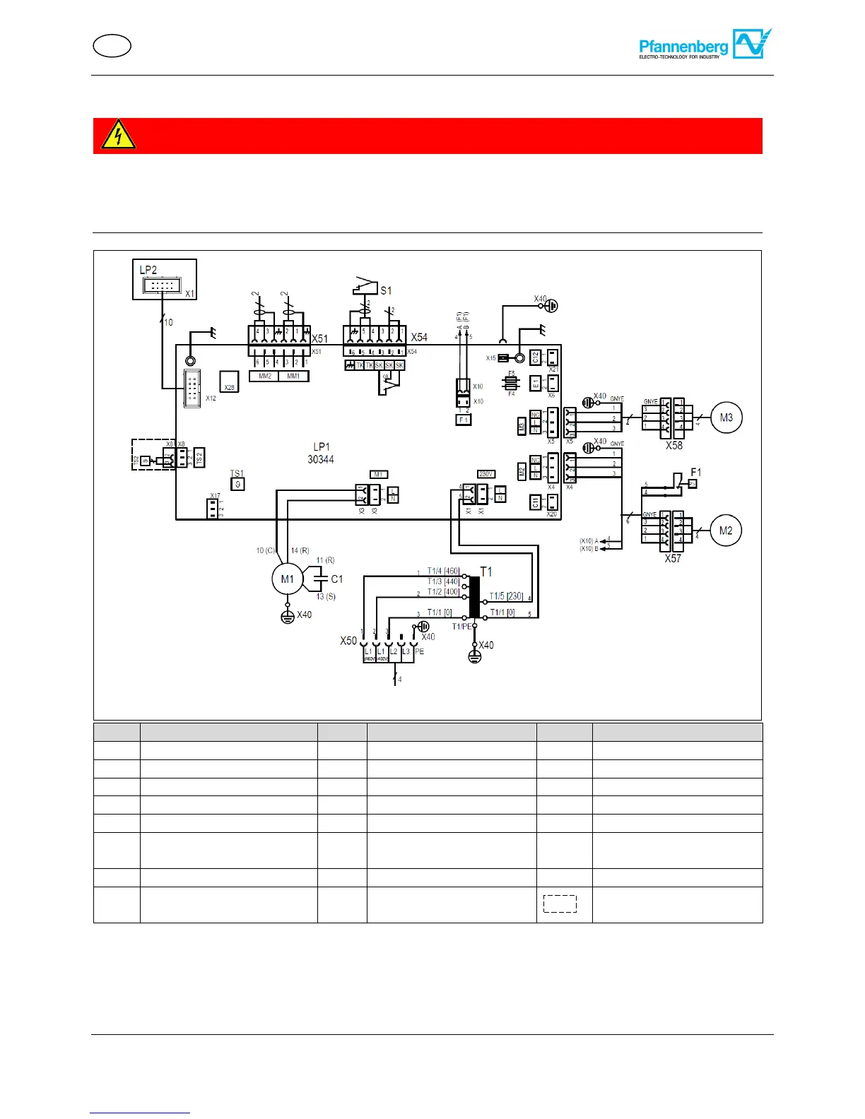
3.5.1 Multi-Controller (MC) electrical circuit diagram
Life-threatening danger due to electric shock
Live units and exposed connection cables can generate an electric shock and cause severe accidents.
Work on electrical connections must be carried out exclusively by trained, qualified electricians.
Ensure that the unit is voltage-free before routing all electrical connections.
Display control unit (MC)
Evaporator fan (internal)
Fault signal contact (1,2)
Door contact/ signal (4,5)
Temperature sensor
(internal)
Temperature sensor
(external)
Multimaster terminal
contact
Door contact+ terminal
contact +Fault indication
Power cable
2x400V-460V 50 Hz
2x400V-460V 60 Hz