Technical Data
21
AUX I/O connector
pin assignment
1)
Must be connected to GND via a floating contact while Extern_Protection is activate (internal pull-up
resistor 5.6 KΩ to +24 V), otherwise the emission will be switched off.
2)
Reserved for future use.
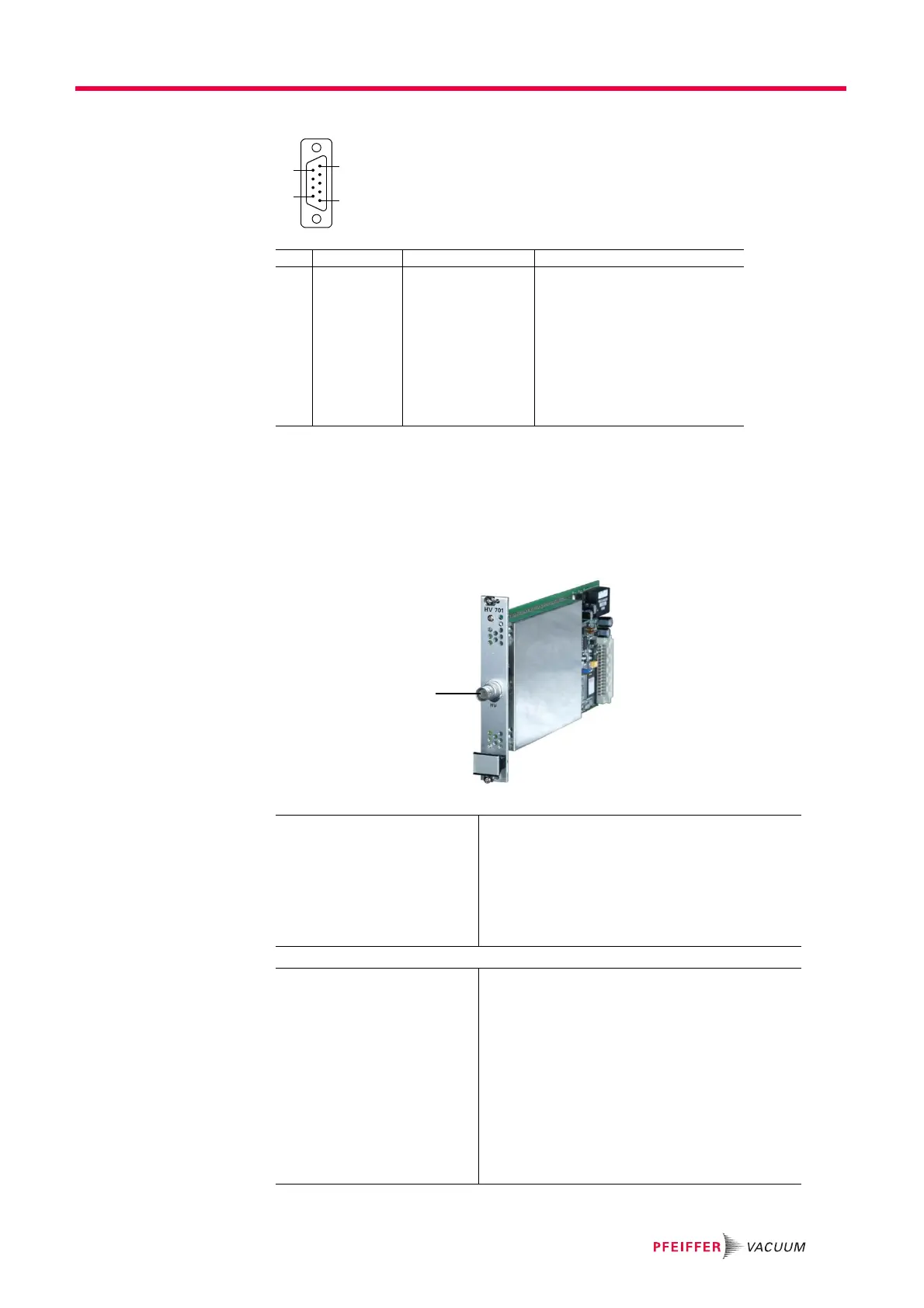
3.5 High Voltage Supply HV 701
D-Sub 9 pin, female
view on IS 716
Pin Signal Signal type Description
1 EXT PROT 24 V digital input
filament protection input
1)
2GND GND
3 DI RES 1 TTL input
2)
4 DI RES 3 TTL input
5 DO RES 1 TTL input
6 DO RES 2 TTL input
7 DO RES 3 TTL input
8 DO RES 4 TTL input
9n.c. –
General
Compatibility system chassis SC 700
Number of slots occupied 1
Modules per system max. 4
Slot No. 33
Weight 0.3 kg
High voltage power supply
SEM voltage HV– –30 … –3500 V (ripple 10 mV typical)
Resolution 219 mV
Load ≥15 MΩ
Current limit
1mA
Source impedance
0 Ω
Settling time 0.3 s (0.1%, switching on, R
L
= 15 MΩ)
Admissible voltage
difference (between
chassis and QMA GND)
0.5 V
HV–
High voltage connector
 Loading...