44 Operation
BG 5186 BEN / C (2013-12) MaxiGauge.om
The upper and lower thresholds are defined in the sec-
ond and third parameter line.
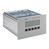
³´μ Control Sensor 3
 Setpoint high 5.00E-05 mbar
 Setpoint low 2.00E-05 mbar
¼½¾ UR-Control off
Defining the threshold values:
• Select the «Setpoint» mode (if applicable) (→ 39)
• Press the [
next] softkey to select the
«
Setpoint high» parameter
• Press the [
®¯] or [¬−] softkey to increase /decrease
the upper threshold value
• Press the [
next] softkey to select the
«
Setpoint low» parameter
• Press the [
®¯] or [¬−] softkey to increase / decrease
the lower threshold value
• Press the [
Return] softkey to return to the
«Measurement» mode
A threshold that is outside the measuring range
is adjusted in such a way that it corresponds to
the lower (upper) range limit.
We recommend setting the threshold ½ decade
above the lower or ½ below the upper threshold
limit.
If both thresholds are outside the measuring
range, they are adjusted analogously in such a
way that a minimum hysteresis is achieved.
For logarithmic gauges, threshold values are
displayed in logarithmic or floating point format,
whereas for linear gauges, they are displayed
in floating point format only (→ Display formats
35).
The modifications are automatically stored in non-volatile
memory.
7.5.3 Defining the
Threshold Values
(
Setpoint)
Figure 35:
«Setpoint» display
e
ay nex
¯
e
urn
 Loading...