8
4.1. Lubricant Filling
– The bearing on the turbomolecular Drag Pump has been
filled with the required amount of lubricant. Changing the
lubricant reservoir should be carried out in accordance
with the instructions in the respective operating
instructions.
– The diaphragm vacuum pump is lubricated for the duration
of its working life.
4.2. Before Starting
The rotor on the turbopump rotates at great
speed. When the high vacuum flange is open
there is a danger of injury and of damage to the
pump resulting from objects falling in.
Therefore never start the turbo pumping station
if the high vacuum flange is open.
➡ With water cooling: Open the cooling water supply and
check flow.
➡ Plug in mains plug.
The main switch 2a on the diaphragm pump must be set to the
Position ”ON”.
Take care when pumping dangerous gases.
Take account of all the safety
recommendations of the gas manufacturer.
4.3. Starting
Operations without DCU 001
➡ Switch on the pumping station with the ON/OFF switch 29
(see Section 2.).
– After a successfully completed (duration approximately 10
seconds) the pumping station will start.
– If, after switching on, the vacuum pump does not start,
please refer to "What To Do In The Case Of Breakdowns ?"
in the respective operating instructions.
– The turbomolecular drag pump runs up automatically. The
running up phase up to the attainment of the rotation
speed switchpoint is dependent on the size of the vacuum
chamber. For the run-up time for the pump please refer to
"Technical Data" in the respective operating instructions.
Before starting the pumping station it is recom-
mended, particularly where the incidence of
water vapour is to be anticipated, to open the
gas ballast valve on the backing pump by hand.
If it is ascertained that the intake pressure
increases or is abnormally high, the valve can be opened
when the pumping station is running. Once the final pressure
has stabilized, the valve can be closed again.
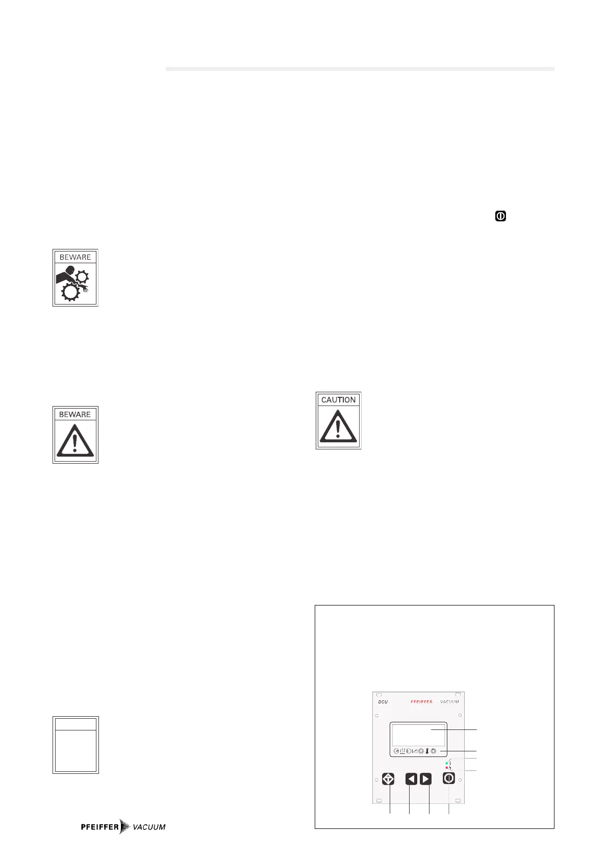
Display And Operating Unit DCU 001
1 LCD Display
2 Status display
3 Key "malfunction
acknowledment”
4 Key ”Left"
5 Key "Right"
4. Operations
6 Key "Pumping Station ON/OFF"
7 Red illuminating diode for
malfunction status
8 Green illuminating diode for
operations status
Operations with DCU 001
The DCU 001 serves to control and monitor the pumping
station.
➡ Switch on the ON/OFF switch 29 (see Section 2.).
➡ Remove bridges 1–4 on the TC 600.
➡ Select [P:794] «Param. Set» and set to «1».
➡ Check relevant set value data and setting commands
(see operating instructions ”Pumping Operations
With The DCU”).
➡ Select [P:023] «Motor TMP» and set to «ON».
➡ Switch on the pumping station with the key on the DCU.
Turbopump Run-Up
If the self-test has been successfully completed, the
turbopump begins to run and the backing pump starts. During
the pre-set run-up time [P:700] the rotation speed switchpoint
[P:701] must be attained. Both parameters can be matched to
the process. If a malfunction code is displayed please refer to
the malfunction code table, Section Kap. 4. in the operating
instructions ”Pumping Operations With The DCU”.
When the malfunction has been acknowledged, the run-up
starting time will be renewed.
Operation with mains voltages 90 - 132 V
With this operations voltage the power output
of Power Pack TPS is reduced by 20% . For this
reason the power take-up on the pump must be
matched correspondingly with the help of a dri-
ve unit DCU via Parameter [P:794].
➡ Select [P:794
]
] «Param. Set» and set to «1».
➡ Select [P:029
]
].
➡ Set to «1» = reduces the power take-up TC 600.
If matching is not carried out, during the run-up phase there
will appear the malfunction signal "E001” or "F007”.
Further details can be found in the following operating
instructions:
– PM 800 477 BN; Display And Operating Unit DCU
– PM 800 547 BN; Pumping Operations With DCU.