4
2.1. For Your Orientation
Symbols used
The following symbols will be used in the illustrations throughout the manual:
Electrical connection
Abbreviations used
TMP = Turbomolecular Pump
DCU = Display and Operating Unit
TC = Electronic Drive Unit
TPS = Mains Power Unit
Position numbers
The same accessory parts have the same position numbers in all illustrations.
Operation instruction in the text
➡ Here you must do something.
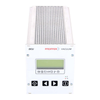
2.2. Product Description
The Display Control Unit DCU is an operating unit for PFEIFFER drive units. It enables control over
all the main parameters of the unit. Additionally, the connection of a vacuum gauge is possible.
DCU 001 = Basic unit without mains power unit
DCU 100/150/200/300/600 = Unit with mains power unit.
Scope of Delivery
– Display Control Unit DCU
– Connecting cable DCU - TC (3m)
– 4 mounting screws
Mechanical Design
The DCU is fitted in a housing suitable for mounting in a 19”/3HE rack.
Connection Options
The DCU provides the following connection options:
– Electronic drive unit for turbopump (X2)
– Pressure gauge (X3).
– Serial interface RS 485.
The units DCU 001, DCU 100 - DCU 600 have been tested and passed by the authorities in
accordance with EN 61010/VDE 0411 “Safety Equipment For Electrical Units”.
2. Understanding The Display and Operating Unit DCU