4.2. General
All function relevant aspects of the pump electronics are illustrated in the form of parameters.
Each parameter has a number and a designation (for example, “720: Vent frequ”).
The value of the parameter is always readable, in some cases also modifiable via the keyboard.
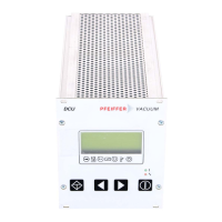
4.3. Switching On The Control Unit
➡ Make the connection to the Serial Interface RS 485.
DCU 001:
➡
Switch on the external supply of the Electronic Drive Unit (for example TPS 100-600).
DCU 100/150/200/300/600:
➡
Switch on the DCU by the switch S1 on the rear side.
➡ In the event of an error message: depress: .
Self-Testing
After switching on, the DCU performs a self-test and also a test on the connected turbo electro-
nics. Run time of the self-test: approx. 20s. During the test a bar appears in the display in line 4
and this shows the progress of this procedure.
•
DDiissppllaayy tteesstt::
All signs in the LC display are shown for a short time in black.
•
LLEEDD tteesstt
: During the whole testing process the red and the green LEDs illuminate.
•
DDCCUU tteesstt
: The DCU hardware is tested.
•
CCoonnnneeccttiioonn ttoo tthhee ttuurrbboo eelleeccttrroonniiccss tteesstt
: The correct connection to the turbo electronics and
their identity are examined.
•
PPaarraammeetteerr tteesstt
: Information regarding the parameters is loaded.
•
IIddeennttiiffiiccaattiioonn ooff tthhee ccoonnnneecctteedd ccoommppoonneennttss
: The designation of the drive unit is displayed.
Providing there are no errors the DCU is now ready to operate.
9
 Loading...