7
3.1. Preparations For Installation
Unauthorised modifications or alterations to the Display Control Unit are not
allowed.
The unit must be fitted in a housing taking account of the ambient conditions (see
section “Technical Data”).
➡ Disconnect mains power plug before installation work.
IInnssttaallllaattiioonn llooccaattiioonn::
Protected against the weather.
The following is applicable for open buildings and operations rooms which are not fully air
conditioned:
TTeemmppeerraattuurree::
+5°C - +40°C.
RReellaattiivvee hhuummiiddiittyy::
5 - 85%, non-condensing.
AAiirr pprreessssuurree::
86 kPa - 106 kPa
3.2. Rack Fitting
The units DCU 001, DCU 100 - DCU 600 are designed to be fitted into a 19”/3HE rack with guide
rails.
➡ For installation secure the front panel to the rack using four fixing screws.
➡ Ensure free convection. The minimum distance to the upper and lower ventilation slits must
be ≥ 50mm.
The ambient temperature in the rack housing must not exceed 40°C.
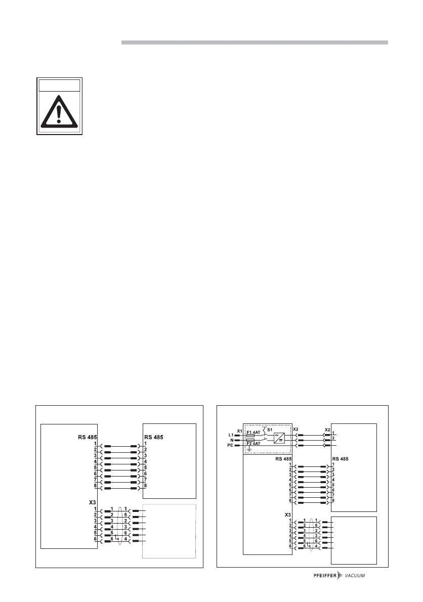
Depending on the version, various connections are provided on the DCU.
3.3. Connecting Diagram
 Loading...