70
Phantom Ultrahigh-speed Camera Manual
connector pinouts
Phantom vxx12
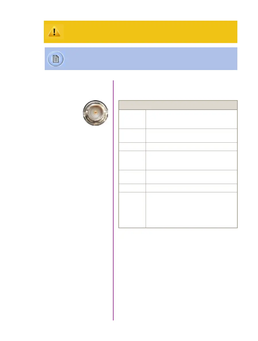
BNC Connectors
NOMENCLATURE / FUNCTION
Trigger Trigger-In / Isolated Input. Active low. Can be
activated by a switch to ground. The trigger pulse
needs to be at least 3 microseconds long.
Time Code In Timecode In / can accept IRIG-B and SMPTE
standards.
I/O 1 Ready / Isolated collector output with 1k pull-up.
I/O 2 F-Sync / +5V maximum threshold, input is also
compatible with TTL levels and must be a properly
terminated, (50-ohms).
I/O 3 Timecode Out / for IRIG-B or SMPTE
timecode.
I/O 4 Strobe / Isolated collector output with 1k pull-up.
HD-SDI
1 & 2
Two HD-SDI ports can acts as identical 4:2:2
HD-SDI ports with one set up to provide an
optional) on-screen display to monitor the
on-camera controls and cameaa operation.
Or, they can be configured as a ‘single 4:4:4
Dual-Link HD-SDI port.
I/O Signal ports
BNC
Use these schematics to build custom cables at your own risk. Mis-wired cables
can cause serious damage to the camera, which is not covered under warranty.
Vision Research recommends only using cables supplied by Vision Research.
These pin-out diagrams refer to the connector on the camera body. Part numbers
indicated are for the cable’s connector.