74
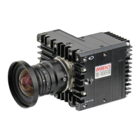
Phantom Ultrahigh-speed Camera Manual
Phantom vxx12
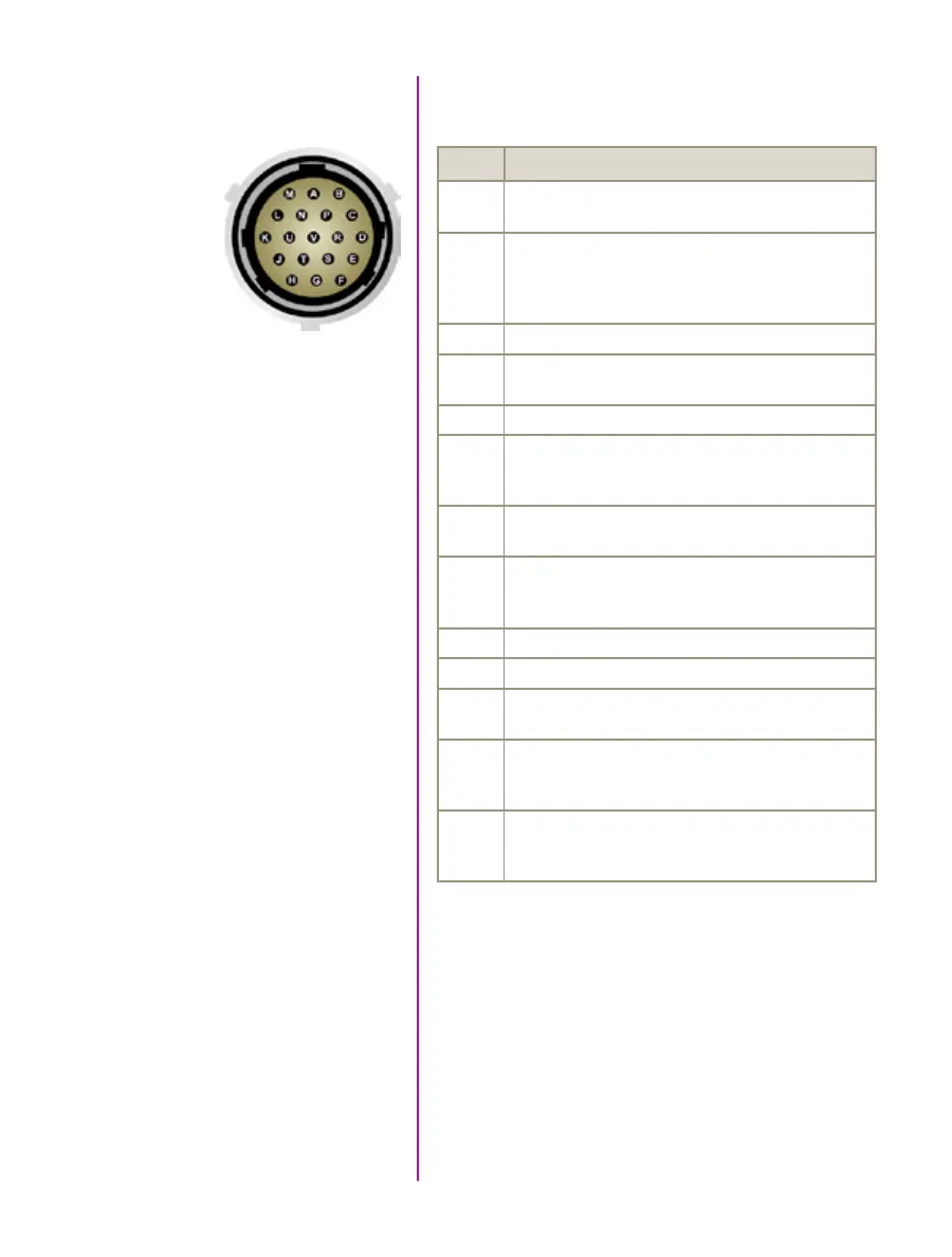
Capture Connector
PIN NOMENCLATURE / FUNCTION
A Event-In / active-low isolated input; signal must be active
when strobe is high, and be 30μs long minimum.
B Trigger / Isolated Input. Active low. Can beactivated
by a switch to ground. The triggerpulse needs to be at
least 3 microseconds long.
Capture cable = Red
C Strobe Out / Isolated collector output with 1k pull-up.
D IRIG- In (Unmodulated) / IRIG-B timecode input.
Capture cable = White
E IRIG GND
F Video Out (Composite) / Standard (non-isolated)
75-ohm output level.
Capture cable = Green
G Video GND (Composite) / Ground / Shield
(for signals: F, and T).
H Serial (RS-232) Ground / Should only be connected
to properly earthed equipment (Serial ports are not
isolated).
J Chassis GND /
K Transmit Data (RS-232) / standard RS-232 level.
L +12-30VDC / DC output (0.5A amp Max.) Typically used
to power break out boxes.
M Power GND / isolates power input and acquisition control
signals from system ground to avoid system ground
loops only, and should not be subject to high voltages.
N Auto-Trigger Output / Pulled low when an auto-trigger
condition detected.
Capture cable = Black
Capture port
19-pin part # PTO6A-14-19S