EasyManuals Logo

Phenix Technologies PM15-2 User Manual

Phenix Technologies PM15-2
21 pages
To Next Page IconTo Next Page
To Previous Page IconTo Previous Page
Page #15 background imageLoading...
Page #15 background image
3-5
SET UP AND OPERATION INSTRUCTIONS
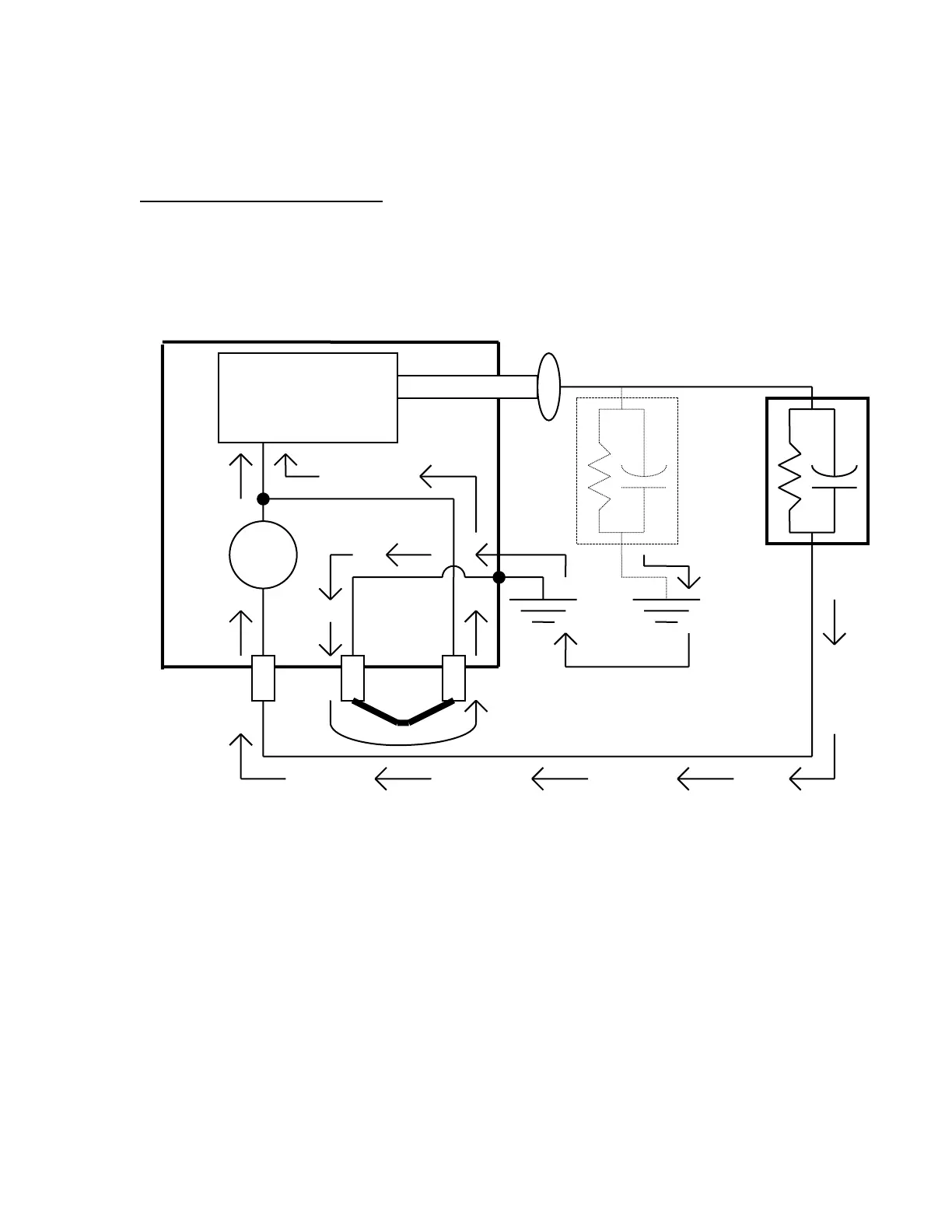
GUARD MODE CONFIGURATION
In this configuration the Guard and Ground is connected together with an external jumper or a
switch internal to the Test Set, depending on the design. Any current associated with the Return
is indicated on the current meter. Any current associated with the Guard bypasses the current
meter. Leakage current through the test specimen is indicated on the current meter. Stray
leakage to earth ground is not indicated on the current meter. This configuration can not be used
if it is not possible to isolate the return side of the Test Specimen from earth ground.
HIGH VOLTAGE
TRANSFORMER
Amp
Guard
Ground
Return
Ground
Test
Specimen
Stray
Leakage
High
Side
Return or Low
Side

Questions and Answers:

Question and Answer IconNeed help?

Do you have a question about the Phenix Technologies PM15-2 and is the answer not in the manual?

Phenix Technologies PM15-2 Specifications

General IconGeneral
BrandPhenix Technologies
ModelPM15-2
CategoryTest Equipment
LanguageEnglish

Related product manuals