Do you have a question about the Phenix Technologies PM15-4A and is the answer not in the manual?
Essential safety and caution guidelines for operating the equipment safely.
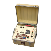
Detailed explanation of the PM15-4A's features and operational capabilities.
Identification and function of front panel controls and their layout.
Details on High Voltage output and Return terminals for specimen connection.
Description of Ground, SX1 Security, USB, and SD card ports, plus HV On/Off controls.
Procedure for the initial charging of the unit's batteries.
Steps for setting up the unit, including grounding and specimen preparation.
Guidance on properly connecting test leads to the specimen for accurate testing.
Detailed explanation of connecting test leads in Normal and Guard modes.
Important caution regarding specimen setup for high resistance measurements.
Explanation of Normal Mode configuration for guard and ground connections.
Explanation of Guard Mode configuration and its impact on current measurement.
Steps for turning on the unit and navigating the main menu options.
Configuring parameters for the Insulation Resistance test, including time, voltage, and current.
Setting temperature compensation parameters and understanding its effects on IR measurements.
Discussion of temperature effects on insulation resistance and leakage current.
Overview of waiting screens for Normal, Guard, and Security Circuit Open states before HV activation.
Display during I.R. testing and options upon test completion like save or print.
Sample printout format for Insulation Resistance test results.
Configuring parameters for the Polarization Index test, including voltage and current.
Option to enable or disable the HV warning buzzer for Polarization Index tests.
Waiting screens displayed before activating HV for Polarization Index tests.
Display during PI testing and options upon test completion.
Sample printout format for Polarization Index test results.
Entering test ID and configuring voltage for Capacitance tests.
Option to enable or disable the HV warning buzzer for Capacitance tests.
Waiting screens before activating HV for Capacitance tests.
Display during Capacitance testing and options upon test completion.
Final page after Capacitance test, offering save or print options.
Sample printout format for Capacitance Measurement test results.
Configuring duration, final voltage, and number of steps for Uniform Step tests.
Setting temperature compensation parameters for Step tests.
Waiting screens before activating HV for Uniform Step tests.
Display during Step testing and options upon test completion.
Sample printout format for Uniform Voltage Step test results.
Configuring voltage and current for Dielectric Absorption Ratio tests.
Setting temperature compensation parameters for D.A.R. tests.
Waiting screens before activating HV for D.A.R. tests.
Waiting screen indicating an open security circuit for D.A.R. tests.
Display during D.A.R. testing.
Final page after D.A.R. test, offering save or print options.
Sample printout format for D.A.R. test results.
Procedure for saving test results to an SD card.
Procedure for printing test results using the onboard thermal printer.
Connecting the unit to a PC via USB for data acquisition.
Overview of available system setup options like company name and clock.
How to enter and save the company name in the system setup.
Setting the unit's clock to 12- or 24-hour format.
Setting the unit's date in day, month, and year format.
Viewing unit version, manufacturing date, tests performed, and calibration dates.
Accessing the calibration function requires a password.
Checking the capacity and remaining space on the inserted SD card.
Recommendations for charging and maintaining Ni-MH batteries for optimal performance.
How to view battery charge and voltage information on the unit.
Guidelines for cleaning the unit's exterior and front panel surfaces.
Performing a printer self-test and understanding its status LED indicators.
Interpreting LED flashes to diagnose printer faults.
Step-by-step instructions for replacing the printer paper roll.
Reference to the drawing number for the unit's schematic diagram.
| Brand | Phenix Technologies |
|---|---|
| Model | PM15-4A |
| Category | Test Equipment |
| Language | English |