4-7
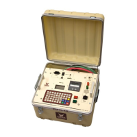
FIGURE 15: HV Waiting Screen – Normal Mode
The HV Waiting Screen (Figure 15) acts as a standby screen, allowing the operator one final chance to
examine the test setup for any discrepancies before activating high voltage. In this screen, the display reads
that the PM15-4A is in Normal Mode. Pressing “G” on the keypad toggles between Normal Mode and Guard
Mode Configuration (See Figure 16).
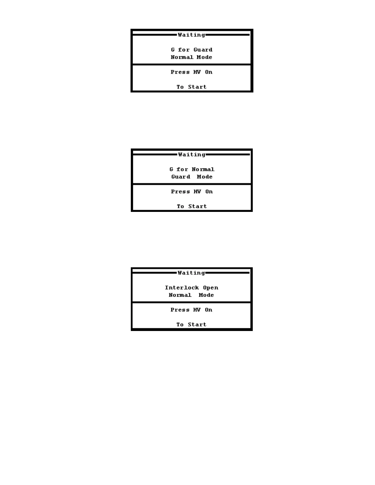
FIGURE 16: HV Waiting Screen – Guard Mode
The screen will display the status of the Guard Mode as shown in Figure 16 once G is pressed to toggle out
of Normal Mode and into Guard Mode operation. In addition, if the security circuit is disconnected,
“INTERLOCK OPEN” will appear at this screen (See Figure 17), disabling the high voltage until the security
circuit is closed.
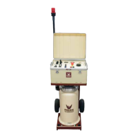
Figure 17: HV Waiting Screen – Security Circuit Open
The HV Waiting Screen will display the status message INTERLOCK OPEN if the security circuit is not
closed on the test set. This status message will appear at the HV Waiting Screen if an open Security Circuit
is detected regardless of what operation mode the PM15-4A is set to (Normal or Guard). If this message is
seen, check the security circuit for loose connections or replace the SX1 plug onto the front panel to close the
security circuit. Press the red HV ON push button to activate the high voltage test. The Polarization Index
Testing Screen will be displayed.