2-1
2. CONTROLS AND CONNECTIONS
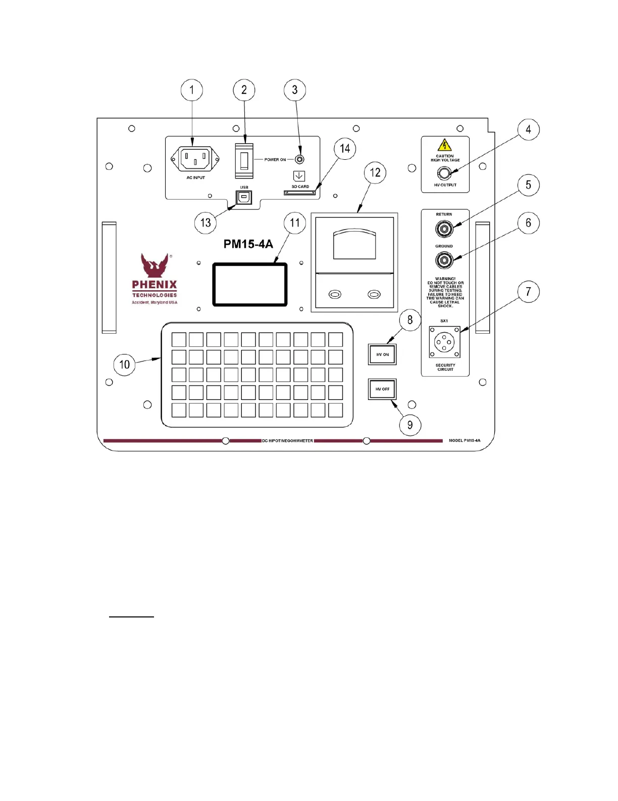
Please refer to Figure 2.1 for identification of front panel components and their function.
FIGURE 2.1: FRONT PANEL LAYOUT
1. AC Input: The provided AC input cable plugs in here to provide AC power to the unit. All fuses are
internal to the unit and should not need replacement under normal conditions.
2. Power Switch: The On/Off rocker switch is used to power on the unit.
3. Power On Indicator Light: This red LED will be lit up when the unit is on.
4. HV Output Terminal: Connect the included HV output cable test lead with clip and insulation boot
here and to the specimen under test.
5. Return Terminal: Leakage current or insulation resistance values associated with this terminal is
measured by the “DC Microammeter”. The low potential side of the test specimen should be
connected to this terminal (red cable provided). When Guard Mode is not activated, the return
terminal is connected internally to ground. All currents associated with return and ground will pass
through the current meter. When Guard Mode is activated, return is isolated from ground and only
currents associated with return will be measured. The test specimen low potential side must be
isolated from ground in order to measure currents to return in Guard Mode.