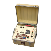
2-2
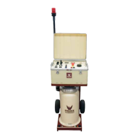
6. Ground Terminal: This terminal is to be connected to the facility ground (black cable provided).
Leakage current or insulation resistance values associated with this binding post terminal may be
either measured by the “DC Microammeter” or bypassed around the “DC Microammeter” depending
on the state of the Guard Mode. If the low potential side of the test specimen connected to
Return cannot or will not be isolated from ground, Guard Mode cannot be used or the current
meter will not function properly.
7. SX1 Security Circuit: This series circuit must be closed in order to activate High Voltage. An
external plug is included to close this circuit or an external customer supplied circuit such as a door
interlock of a testing room can be connected to it for use.
8. HV On Push Button: Push this button for HV test when prompted by the onboard display.
9. HV Off Push Button: Push this button to turn off High Voltage to end testing.
10. Keypad: Keyboard to enter information on test data and to navigate the User Interface.
11. Display: Displays User Interface menus and test results.
12. Printer: Used to print test reports and results of HV testing.
13. USB Port: Used to connect the test set to a PC for Data Acquisition using Phenix Windows Test
Software (Under Development).
14. SD Card Slot: Used to save test data to an SD Card.