EasyManua.ls Logo

Phenix Technologies BK130 User Manual

Phenix Technologies BK130
39 pages
To Next Page IconTo Next Page
Page #1 background imageLoading...
Page #1 background image
BK-130
USER’S MANUAL
AC DIELECTRIC TEST SET
600 SERIES
Model Number
BK130/36
Version
5.1
Phenix Technologies, Inc.
75 Speicher Drive
Accident, Maryland 21520
Copyright © Phenix Technologies, Inc.
Rev 2/9/2015 nab
Question and Answer IconNeed help?

Do you have a question about the Phenix Technologies BK130 and is the answer not in the manual?

Phenix Technologies BK130 Specifications

General IconGeneral
BrandPhenix Technologies
ModelBK130
CategoryTest Equipment
LanguageEnglish

Summary

DANGER / GENERAL SAFETY PRECAUTIONS

SECTION 1: TECHNICAL SPECIFICATIONS

SECTION 2: UNCRATING PROCEDURE

SECTION 3: CONTROLS AND INDICATORS

SECTION 4: INITIAL SET-UP—MECHANICAL / ELECTRICAL

SECTION 5: OPERATIONAL VERIFICATION PROCEDURE

GENERAL TEST PROCEDURE

SECTION 6: GUARD-GROUND-RETURN CONNECTIONS

SECTION 7: CALIBRATION

Output Voltmeter Calibration

Adjusts the output voltmeter reading using potentiometers R1 for 36 kV and R2 for 130 kV.

Output Currentmeter Calibration

Calibrates the output currentmeter for various ranges by adjusting potentiometers R204, R203, R202, and R201.

Overcurrent Calibration

Recalibrates the overcurrent circuit trip points for minimum (18mA) and maximum (198mA) settings.

Range Overcurrent Calibration

Sets overcurrent trip for ranges to 112% of full range current using R235.

SECTION 8: TROUBLESHOOTING

High Voltage Cannot Be Turned On

Troubleshooting steps for issues preventing high voltage activation, like emergency stops or interlocks.

Voltage Control Inoperable

Diagnoses problems with voltage control, including power issues, cables, or faulty regulators.

Overload Trip Inoperable

Addresses malfunctions in the overload trip feature, including sensitivity and component checks.

Currentmeter Inoperable

Steps to diagnose and fix an inoperable currentmeter, checking connections and components.

Voltmeter Inoperable

Troubleshooting an inoperable voltmeter, including cable, meter, and switch issues.

No Output Voltage from High Voltage Section

Identifies causes for no output voltage, such as metering circuits or transformer issues.

SECTION 9: MECHANICAL MAINTENANCE

Surface Maintenance

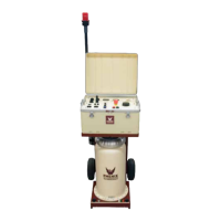
Cleaning exterior surfaces and inspecting for oil leaks on the unit.

Control Box and Regulator Section Maintenance

Annual inspection and cleaning of control assembly, regulator, and brushes.

Transformer Oil Maintenance

Guidelines for checking transformer oil purity at regular intervals.

SECTION 11: TRANSPORTING / STORAGE OF EQUIPMENT

Transporting the Control Box / Regulator Section

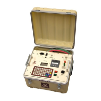
Anchoring and covering the control box/regulator section for safe shipment.

Transporting Interconnect Cables

Covering interconnect cable connectors to prevent foreign matter entry during transport.

Transporting the High Voltage Transformer

Anchoring, covering, and cleaning the HV transformer for safe transport.

Equipment Storage Recommendations

Guidelines for storing equipment in a dry environment and protecting it from conditions.

SECTION 12: CIRCUIT DIAGRAM SYMBOLS

SECTION 13: ELECTRICAL DIAGRAMS

SECTION 14: PARTS ORDERING INFORMATION

SECTION 15: RECOMMENDED SPARE PARTS

SECTION 16: BK-130 PARTS LIST

SECTION 17: RETURNED MATERIAL

SECTION 18: CUSTOMER COMMENTS/SUGGESTIONS

Related product manuals