BK-130
3-2
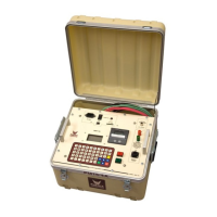
CONTROLS AND INDICATORS
Descriptions are keyed to Figure 3-1.
1. Main Power Indicator.
2. Main Power Circuit Breaker. Interrupts all power into set.
3. F1(120V) F1,2 (220V) - Control Power Fuse/Fuses.
4. Transformer Power Circuit Breaker - Interrupts power to HV Transformer. Breaker must
be on to activate High Voltage.
5. Measurement Divider Switch - Selects proper overload and voltmeter circuitry for the H.V. output
terminal being used. Match switch setting to output being used on HV transformer.
6. Overload Trip - Use for presetting desired Overcurrent trip setting. Range
approximately 10-110% of rated current.
7. Reset - Will light when Overcurrent trip setting is exceeded. Push to reset. Lamp must be
extinguished for H.V. ON.
8. Emergency Off – Push down to stop test immediately. Button must be pulled up to activate High
Voltage Output.
9. High Voltage On Switch and Indicator Lamp - Turns on H.V. when Ready indicator is illuminated.
10. High Voltage Off Switch and Indicator Lamp - Turns H.V. off, indicator shows when all conditions
are met to turn H.V. ON. (External Interlock closed, Reset Lamp off, Emergency Off Button pulled up,
Voltage Control at Zero).
11. Voltage Control - Adjusts Output Voltage and must be set at zero to turn High Voltage on.
12. Currentmeter Range Selector.
13. Output Currentmeter.
14. Output Voltmeter.
15. SX1 External Interlock - Provides for user connection of external interlock or auxiliary safety control
device such as Emergency Off Switch, Gate Switch, Footswitch, Dead man Switch, etc. Included plug
has shorting jumper installed to complete circuit. Jumper must be removed and cable connected to
user supplied device by user if desired to use this provision. Only non-energized switch or dry relay
contact devices may be used. This is a series 120VAC circuit that must remain closed for High
Voltage to be activated.
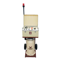
16. Output to Transformer - High Voltage Transformer power connection.
17. Main Input – Main input cable connects here.
18. Ground Terminal.
19. TX1 – Signal/ Metering cable between H.V. Unit and controls connects here.
20. Test Cell Timer. Press START/RESET to start the timer after test voltage has been reached. Press
START/RESET again to reset timer to the original setting. Press HV OFF BYPASS to allow high
voltage to remain on after the timer has expired. Test time can be set using the buttons on the face of
the timer.