4-16
temperature, usually (40°C or 68°F). The PM15-4A has the capability to perform this calculation automatically
by entering the test object temperature. The built in printer function allows the operator to document the
results with a date-time stamp showing both the Raw test results without temperature correction as well as
the Corrected final value side by side.
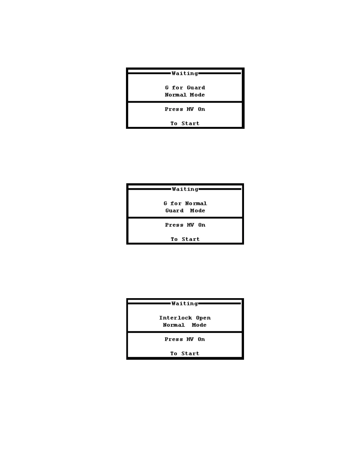
FIGURE 34: HV Waiting Screen – Normal Mode
The HV Waiting Screen (Figure 34) acts as a standby screen, allowing the operator one final chance to
examine the test setup for any discrepancies before activating high voltage. In this screen, the display reads
that the PM15-4A is in Normal Mode. Pressing “G” on the keypad toggles between Normal Mode and Guard
Mode Configuration. (See Figure 35)
FIGURE 35: HV Waiting Screen – Guard Mode
The screen will display the status of the Guard Mode as shown in Figure 35 once G is pressed to toggle out
of Normal Mode and into Guard Mode operation. In addition, if the security circuit is disconnected,
INTERLOCK OPEN will appear at this screen (See Figure 36), disabling the high voltage until the security
circuit is closed.
Figure 36: HV Waiting Screen – Security Circuit Open
The HV Waiting Screen will display the status message INTERLOCK OPEN if the security circuit is not
closed on the test set. This status message will appear at the HV Waiting Screen if an open Security Circuit
is detected regardless of what operation mode the PM15-4A is set to (Normal or Guard). If this message is
seen, check the security circuit for loose connections or replace the SX1 plug onto the front panel to close the
security circuit. Press the red HV ON push button to activate the high voltage test. The Uniform Step Testing
Screen will be displayed.