4-17
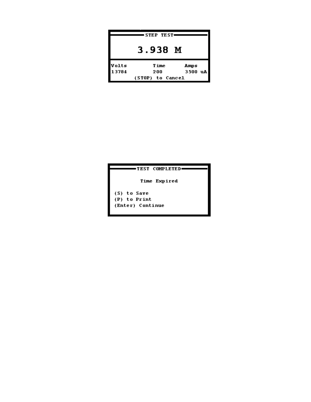
FIGURE 37: Uniform Step Testing Screen
The Step Test Testing Screen (Figure 37) will display real-time data on voltage, current and resistance. The
Intra-Test Printing function works differently during the Step test. If “P” is entered during a test, the printer will
print resistance results for every step until the test is complete. Otherwise pressing “P” at the Test
Completion page will print the results of the Step test with each of the voltage step results all at once. After
the test is complete, the test complete screen will display (Figure 38) and the user may print or save the
results. Either printing or saving to the SD Card will give the operator results for every step in addition to the
final resistance reading.
NOTE: Pressing the HV OFF button OR the STOP key on the keypad will end the test early.
FIGURE 38: Test Completion Page
The Test Completion Page (Figure 38) is displayed upon completion of the Step test, after the previously
entered test time has passed. The operator is given the choice to save or print the final test data. The
PM15-4A will discharge the test object upon test completion.
WARNING; Depending on the size of load capacitance, dangerous voltages may be present at the end of the
lead for a few moments. Always ground any high voltage leads before removing leads from test object. The
use of appropriately rated discharge and grounding devices is recommended to ensure that the test object is
fully discharged and grounded before removing leads after testing is complete. A minimum discharge time
which is approximately 4 times that of the voltage application duration is recommended.