4-19
4.1.5 Dielectric Absorption Ratio (D.A.R. Test)
Figure 40: Dielectric Absorption Ratio Test I.D. Screen
Enter an alphanumeric test identification (or leave blank) and press enter.
In good insulation systems, it is expected that the insulation resistance increases as the time dependant
charging currents approach zero. Generally, insulation systems that are degraded show low resistance values
even after a considerable amount of time has elapsed. The time dependant Dielectric Absorption Ratio can
provide a good indication whether the insulation system has a problem. By taking a resistance measurement
at 30s and a resistance measurement at 60s and calculating the ratio of the two readings, a determination of
the insulation quality can be made. Typically D.A.R. values lower than 1.25 warrant further testing and
evaluation.
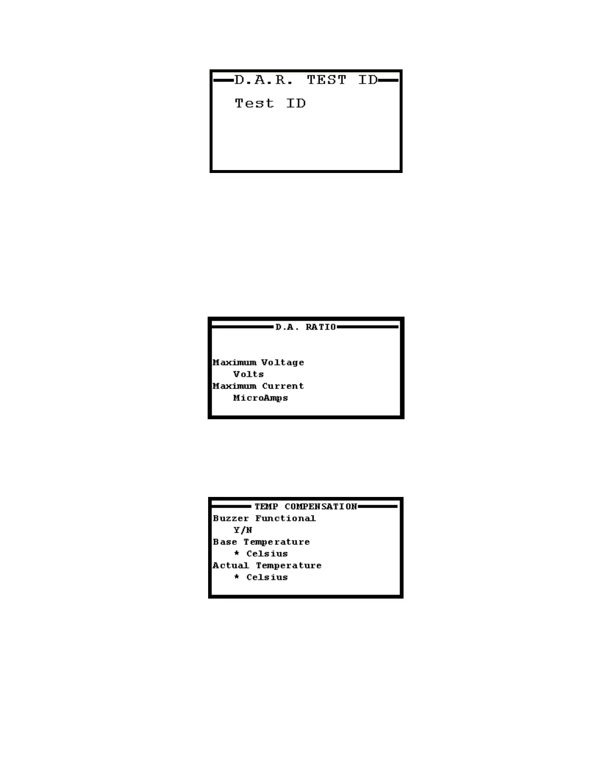
FIGURE 41: Dielectric Absorption Ratio Setup Screen
At the Dielectric Absorption Ratio Setup Screen (Figure 41), enter the maximum voltage to apply and the
maximum allowed current for the Overcurrent Trip. Press Enter to cycle through the Temperature
Compensation Setup Screen.
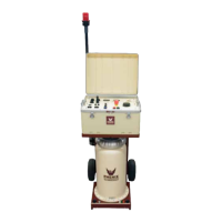
FIGURE 42: Temperature Compensation Setup Screen
At the Temperature Compensation Setup Screen (Figure 42), the operator can choose to activate the internal
buzzer to sound during the test. Inputs are Y for buzzer on and N for buzzer off. Users can then define a
base temperature to correct resistance measurements to, as well as the actual temperature of the test object.
These fields must be completed, as leaving them blank does not bypass the temperature compensation
function of the unit. It is recommended not to correct to a temperature more than ± 20°C from the test
objects temperature, as this could cause significant error in the resistance reading. Once the Temperature
Compensation screen is filled out, press Enter to bring up the HV Waiting Screen.