www.phenomenex.com
1
© 2009 Phenomenex, Inc. All rights reserved.
A. Capillary GC Installation with a Traditional GC Nut
Note: GC columns do not have a specific directional flow when received from the manufacturer. Upon initial use of your new Zebron
™
column, Phenomenex recommends
the practice of dedicating one specific end of the column for injector installation only. This is particularly important when dealing with active/caustic or contaminating
compounds. If these compounds are routinely injected onto the column, degradation of the phase will occur - leading to higher bleed. A typical first step to remedying
(removing) this bleed would be to trim 10 cm from the front (injector) end of the column and keep trimming this inlet end of the column as necessary. Trying to remedy any
bleed issues by trimming the column may not work if both ends have been interchangeably installed into the inlet.
Injector Installation
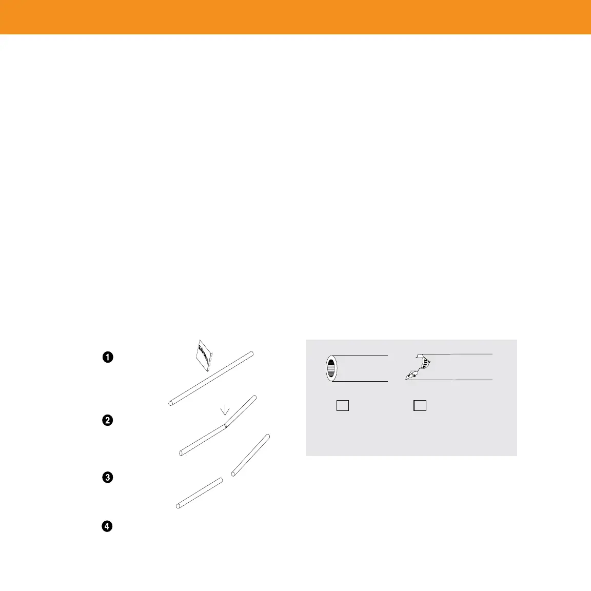
Place a capillary nut and ferrule on the injector end of the GC column, 1.
allowing a section of column to protrude. Trim one to two centimeters
(cm) from the protruding end to remove ferrule contamination that may
have entered the column (Figure 1). Inspect the cut with a magnifier to
ensure that a smooth, clean, square-cut edge has been made – cut again
if necessary (Figure 2).
Carefully hang the column in the GC oven, being cautious not to scratch or 2.
damage the polyimide coating on the capillary tubing. Rotate the column
to avoid sharp bends of the capillary column and any contact of the
column with oven surfaces.
Insert the column into the injector exactly the correct distance specified 3.
in the instrument manual. Tighten the ferrule nut finger-tight then ½ turn
with a wrench. If the column can still be moved, tighten another ¼ turn
until the column is secure.
Adjust the carrier gas.4.
Detector Installation
Note: For users with sensitive detectors such as MS and ECD, column
conditioning steps should be performed before installing the column to prevent
contamination and frequent maintenance of the detector.
Place the column nut and ferrule past the end of the column and cut a 1.
centimeter or two off the end of the column (Figure 1). Be sure that the
ferrule is the right size and pointing in the correct direction. Inspect the
cut with a magnifier and ensure that the cut is square and smooth (Figure
2). Cut again if needed.
Insert the outlet end of the column into the detector exactly the distance 2.
prescribed in the instrument manual. Distances will vary between
detectors. Tighten the ferrule nut finger-tight then ½ turn with a wrench.
If the column can still be moved, tighten another ¼ turn until the column
is secure.
Inspect the column connections for leaks using an electronic leak 3.
detector. Leaks at the inlet end may introduce oxygen to the column that
will result in increased column bleed and damage to the column phase.
Figure 1: Cutting Fused Silica Tubing Figure 2: Proper and Improper Cut Capillary End
score capillary with
smooth edge of
wafer at a 45° angle
apply force in a
downward direction
tubing should break
cleanly
inspect cut with a
magnifying glass
b
a
Examples of: (a) A Properly Cut Fused Silica Column End
(b) An Improperly Cut End
Correct Incorrect
4
X
GC Column Installation
 Loading...