8
Mechanical Instructions
107T6 CRT
Go to cover page
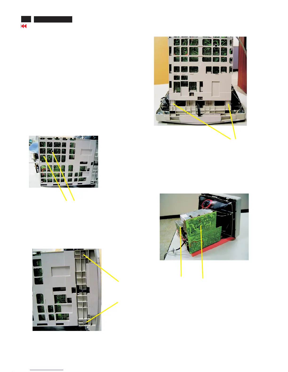
Screw
Fig. 6
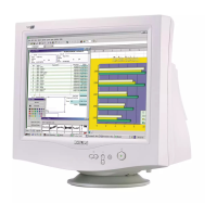
Press clip
Fig. 6
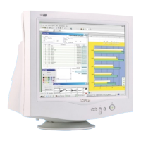
Video panel
Main panel
Fig. 9 SERVICE POSITION
=======>
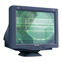
Pull-up
Fig. 8
4. Main panel with Bottom Tray
-Remove 2 screws for disconnect the Bottom tray as Fig. 6.
-Remove the bottom tray on press right and left side clip from
fig. 7 to fig. 8.
5. SERVICE POSITION
-reconnect connectors, some wires and panels (chassis),
service position can be available for DC/AC measurement
as shown in Fig. 9.