4-1 PL14.12-A_DC
CABINET DISASSEMBLY INSTRUCTIONS
Screw Torque Specification
* For reference
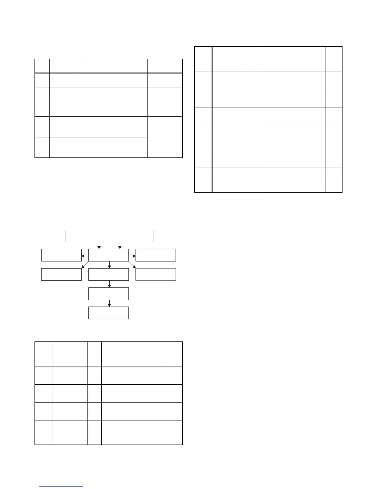
1. Disassembly Flowchart
This flowchart indicates the disassembly steps for the
cabinet parts and the CBA in order to gain access
to items to be serviced. When reassembling, follow
the steps in reverse order. Bend, route and dress
the cables as they were.
2. Disassembly Method
*1: 32PFL4909/F7, 32PFL4909/F8
*2: 32PFL4609/F7
Note:
(1) Order of steps in procedure. When reassembling,
follow the steps in reverse order. These numbers
are also used as the Identification (location) No. of
parts in figures.
(2) Parts to be removed or installed.
(3) Fig. No. showing procedure of part location
(4) Identification of parts to be removed, unhooked,
unlocked, released, unplugged, unclamped, or
desoldered.
P = Spring, L = Locking Tab, S = Screw,
H = Hex Screw, CN = Connector
e.g. 2(S-2) = two Screws of (S-2),
2(L-2) = two Locking Tabs of (L-2)
(5) Refer to the following “Reference Notes in the
Table.”
Ref.
No.
Part
Number
Part Name
Tightening
Torque
L9 GBHP3120
SCREW BIND BLACK_NI
+P-TITE M3X12.0
5.2±0.9lb·in
L23 GBJS3060
SCREW BIND 3CHROM
+S-TITE M3X6.0
4.3±0.9lb·in
L27 GBHS3080
SCREW BIND BLACK_NI
+S-TITE M3X8.0
5.2±0.9lb·in
SSK1 1ESA34003
STAND SCREW KIT
(SCREW BIND BLACK_NI
+P-TITE M4X25.0)
(approx.
8.7±0.9lb·in)
*
SSK1 1ESA34004
STAND SCREW KIT
(SCREW BIND BLACK_NI
+P-TITE M4X14.0)
Step/
Loc.
No.
Part
Fig.
No.
Removal Note
[1]
*1
Stand Base
Assembly
D1 3(S-1), Stand Neck ---
[1]
*2
Stand
Assembly
D1 3(S-1) ---
[2]
Rear
Cabinet
D1 11(S-2), 7(S-3) ---
[3]
Power
Supply
CBA
D2
D5
4(S-4), CN501,
CN601, CN1001
---
[4] Digital Main
CBA Unit
[3] Power Supply
CBA
[2] Rear Cabinet
[6] Stand Holder
[5] Speaker
[8] IR Sensor
CBA Unit
[9] LCD Panel
Assembly
[7] Function
CBA Unit
[1] Stand
Assembly*
1
[1] Stand Base
Assembly*
2
[4]
Digital Main
CBA Unit
D2
D5
4(S-5), CN3105,
CN3801, CN3904,
Jack Holder
---
[5] Speaker D3 ---------------- ---
[6]
Stand
Holder
D3 2(S-6) ---
[7]
Function
CBA Unit
D3
D5
CN4051, Function
Knob, Knob Frame,
Hook
2
[8]
IR Sensor
CBA Unit
D3
D5
Sensor Shield, Hook 2
[9]
LCD Panel
Assembly
D4
Decoration Plate, LED
Lens, Leading Edge
Cover, Hook
1
↓
(1)
↓
(2)
↓
(3)
↓
(4)
↓
(5)
Step/
Loc.
No.
Part
Fig.
No.
Removal Note